
Estimated Study Time: 23 minutes
Consideration Issues
A busbar protection must be capable of clearing all phase-to-earth faults, and in the case where they can occur, phase-to-phase faults. Policy regarding fault clearance times required from busbar protection varies from utility to utility. Due to the fact that the short-circuit levels of bus bars are often very high, busbar fault clearance times are required to be as short as possible.
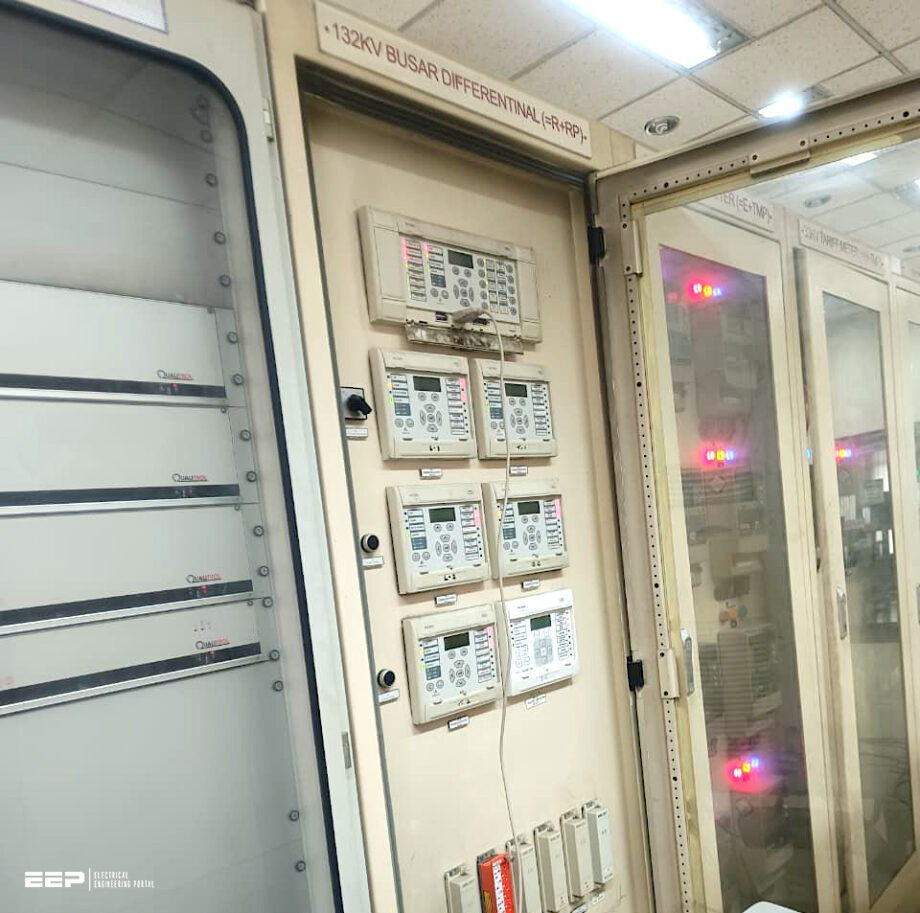 What if busbar protection is not capable of clearing all phase-to-earth faults (photo credit: Saddam Hossen via Linkedin)
This may vary from, i.e., 100 ms for some 400 kV metal-clad substations up to 600 ms for lower voltage levels.
The protection must remain stable during through-faults (outside the bus-zone), especially in the case of CT saturation and switching operations. Due to the high ratio of through-faults to bus-zone faults, busbar protection is called upon to stabilise many more times than it has to operate.
With the exception of simple busbar configuration (single busbar and one breaker a half), these boundaries are not fixed, rather depend on the position of the selection isolators.
For this reason, the busbar protection must possess an accurate replica of the station’s primary configuration.
- High Reliability (or When It’s Not)
- Problem With CT Saturation
- Outflow at Occurrence of Internal Fault:
- Double Busbar Configuration
- Multi Busbar Configuration
- One and a Half Breaker Busbar Configuration
- Gas Insulated Substation (GIS) Specification
- Switching of Internal Terminals
- CT Disconnection for Bus Section and Bus Coupler Current Transformer Cores
- CT Location for Cable Outlet or Earthing Switch for Line
- Attachment (PDF) 🔗 Download ‘Guidelines to Protection Of Synchronous Generators and Induction Generators’
1. High Reliability (or When It’s Not)
Busbar protection, the main protection is a unit protection. Hence there is no particular need for coordination of the main protection. As a general rule the backup protection (impedance relay for connected power transformer or distance protection) second zone should at least reach 20% over the next station to ensure backup for busbar fault.
Many countries are pleased to use instantaneous trip for fault current above rated current, but some countries wants the busbar relay to always trip for the lowest infeed power i.e.- normally down to 20% of rated current.
Building a busbar protection scheme with precision and dependability in mind is crucial. According to the reviewed literature, differential protection systems are employed by larger substations, whereas overcurrent relays are utilized by smaller distribution substations that handle medium voltage to safeguard the busbar.
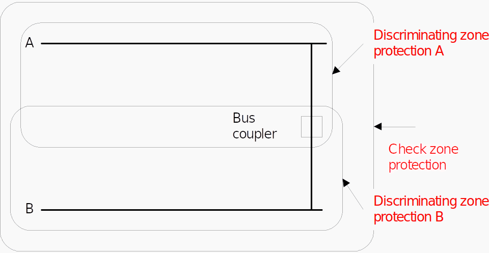
To prevent unwanted operation a check zone is used as shown in Figure 1.
Figure 1 – Protection Scheme for Double Busbar
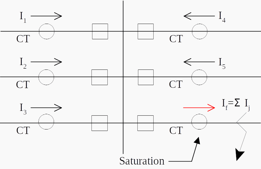
2. Problem With CT Saturation
There is a terminal which current flows toward the fault point against an external fault as shown in Figure 3 below. As CT at the terminal may be saturated due to large out-coming current, the busbar protection has possibility not to operate correctly.
One of the countermeasures of this phenomenon is known as high impedance differential protection described this technical article. And, for analogue relays, traditionally adaptive phase comparison differential principle is strong countermeasure against CT saturation.
The value of the stabilising resistor is chosen such that the voltage drop across the relay circuit is insufficient to operate the relay for faults outside the protection zone, i.e., is high compared with the secondary winding resistance of saturated CT and resistance of the leads in the parallel circuit.
Figure 2 – A.C. circuits for high impedance circulating current scheme for duplicate busbars

If CT secondary switching is applied, a check zone measurement is usually added to the discriminating measurement, requiring separate CT cores. The check zone measurement is an overall measurement taken over the whole substation and is by definition independent of the isolators’ positions and auxiliary contacts.
A trip command is only given when both a discriminating measurement and check systems operate.
Furthermore, the stability of the protection is dependent on the fault level. This simple form of high impedance busbar protection is widely used for simple busbar configurations but not really suitable for complex busbar arrangements.
For digital relays, several principles, for example, no-change detection of differential current is used to measure against CT saturation. The digital busbar protection applying Rogowski CT or non-conventional CT, which is saturation free, is ultimate measure.
Figure 3 – CT Saturation
3.Outflow at Occurrence of Internal Fault
3.1 Double Busbar Configuration
In a double busbar with four sections, there may be an outflow terminal when an internal fault occurs as shown in the Figure 4.
Figure 4 – Outflows at Occurrence of a Busbar Fault in Double Busbar Configuration
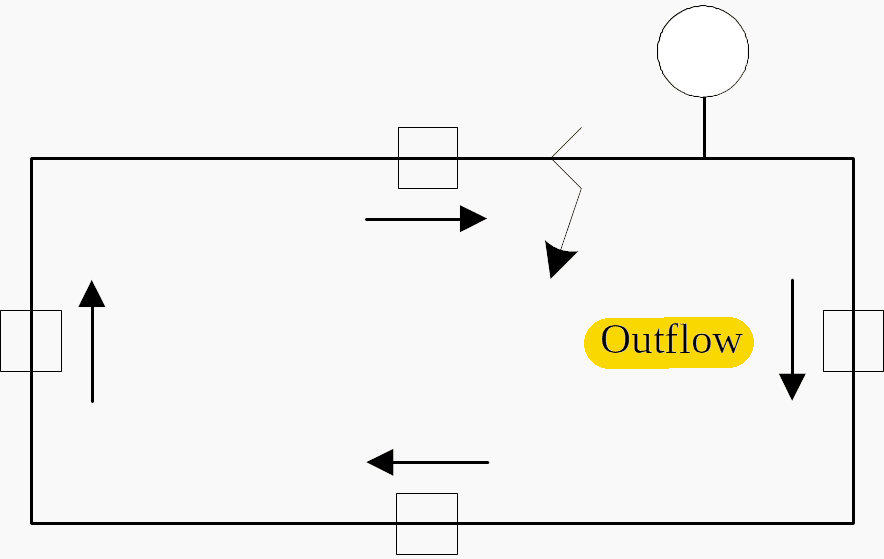
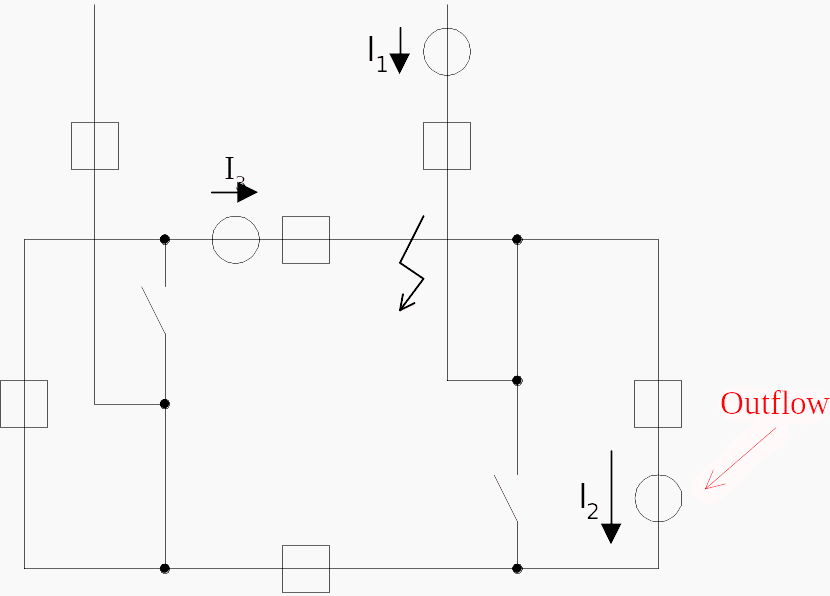
Figure 5 shows the outflow for busbar internal fault. Considering the worst case, half of fault current may flow out from the faulty busbar zone.
Figure 5 – Occurrences on Outflow at Busbar Fault for Double Busbar Configuration
For current differential relay, outflow must be considered to determine the characteristic as shown in Figure 6. The slope or the percentage ratio of the operational current, i.e. differential current, to the restraining current, i.e. the summation of current must be lower than the worst outflow case.
Figure 6 – Percentage Characteristic
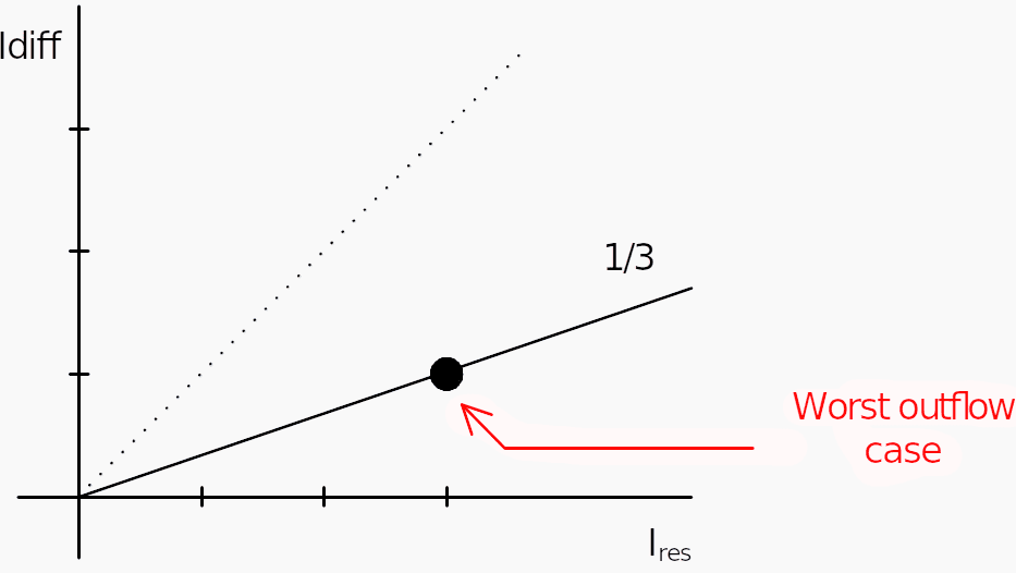
Following is calculation based on the worst case of outflow.
- Idiff = I1 + I2 + I3 = I + (−I) + I = I
- Ires = |I1| + |I2| + |I3| = 3 × I
- Idiff / Ires = 1/3 ≥ K
Hence, K = 1/3
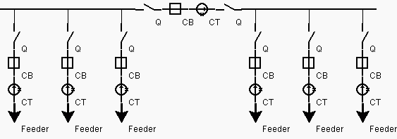
3.2 Multi Busbar Configuration
In a substation there are:
- n bars (Independent bars)
- A minimum internal short-circuit value (Icc min (1 bar))
- A maximum load for a bar (IloadMax (1 bar)).
Figure 7 – Substation configuration
The worst case is:
- When all these buses are independent (bus sectionalizers open)
- The maximum load is on all the buses (biggest bias current)
- The internal short-circuit value is minimum.
Figure 8 – Substation configuration
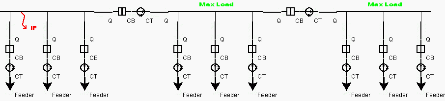
During the internal fault:
- the bias current is: Icc min (1 bar) + (n−1) × IloadMax (1 bar)
- the differential current is: Icc min (1 bar)
Figure 9 – Currents during the internal fault
Thus the biggest slope for the Check Zone to detect the fault is:
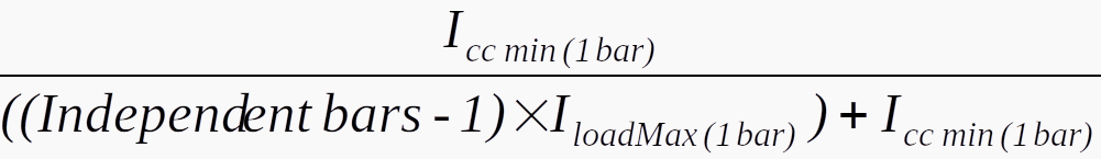
For example if there are 3 buses and Icc min = IloadMax, then the slope must be below 33%.
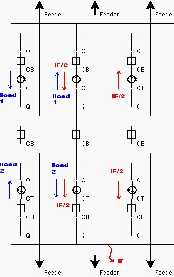
3.3 One and a Half Breaker Busbar Configuration
For a one and half breaker scheme there are:
- 2 bars (Independent bars)
- A minimum internal short-circuit value (Icc min (1 bar))
- A maximum load for a bar (IloadMax (1 bar)).
The worst case is:
- When the is split in 2 and goes as well through the opposite bar
- The maximum load is on the 2 buses (biggest bias current)
- The internal short-circuit value is minimum.
During the internal fault:
- The CZ bias current is: Icc min (1 bar) + 4 × IloadMax (1 bar)
- The CZ differential current is: Icc min (1 bar)
Thus the biggest slope for the Check Zone to detect the fault is:
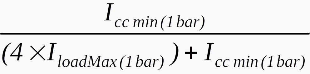
If for example: Icc min = IloadMax, the slope must be below 20%.
3.4 Gas Insulated Substation (GIS) Specification
It is compulsory to clear a busbar fault in a Gas Insulated Substation (GIS) within a certain limited time to avoid the arc damaging the gas chamber integrity as a hole in the chamber or seals. Even minor loss of gas chamber integrity can lead to further explosions. Minor damage can take several months to repair involving major substation outage of the damaged and adjacent bays.
The longest total fault clearance time (not just the relay tripping time) should cover the breaker failure mode, which is mostly dependant on the longest Circuit Breaker Operating Time (CBOT).
As an example, if the longest clearance time that can be permitted is 230 ms, the evaluation of the time coordination is as follows:
Table 1 – The evaluation of the time coordination
| Fast Breaker | Slow Breaker | |
| Tripping time (sub-cycle): | 20ms max | 20ms max |
| CBOT | 30ms | 60ms |
| Total Clearance time: | 50ms | 80ms |
If a circuit breaker failure happens, the following sequence of events occurs:
Table 2 – Sequence of events in the case of a circuit breaker failure
| Fast Breaker | Slow Breaker | Slow Breaker and Reduced Timer | |
| Tripping time (sub-cycle): | 20ms max | 20ms max | 20ms max |
| CBOT (not counted in total clearance time) | (30ms) | (60ms) | (60ms) |
| Back trip timer * | 100ms | 150ms | 100ms |
| Relay to operate | 5ms | 5ms | 5ms |
| CBOT: | 30ms | 60ms | 60ms |
| Total Clearance time: | 155ms (fine) | 235ms (too long*) | 185ms |
* The Back trip timer has to be reduced in the case of slow CBOT to 100ms to keep 45ms margin (100ms is fine because the reset time of the 50BF shall be around 20ms).
It is therefore clear that GIS busbar protection must generally be subcycle performance and must include a fast reset circuit breaker failure protection.
3.5 Switching of Internal Terminals
Connections of lines are sometimes changed in the double busbar. And, the busbar protection is needed to change input terminals to trip selectively every time a connection bus is changed. Especially in High Impedance Differential Relay, the means of changing input terminal change directly CT secondary circuit.
When disconnector auxiliary switches or repeat relays are used for switching CT secondary circuits, they shall also be used to short to earth and disconnect the CT secondary wiring from any common bus wiring when the primary circuit is isolated.
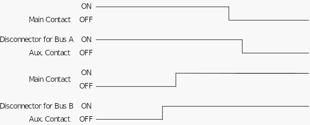
The operating sequence of disconnector auxiliary switches or disconnector repeat relay contacts used in CT secondary circuits MUST be such that the auxiliary switches or repeat relay contacts operate as shown in Figure 10:
- Before reaching the pre-arcing distance on closing the disconnector.
- After the pre-arcing distance has been exceeded on opening the disconnector.
Combinations of normally open and normally closed auxiliary switches or repeat relay contacts from the same disconnector shall `break’ before `make’ both for opening and closing the disconnector.
The result is that the secondary circuits of the two zones concerned are briefly paralleled while the circuit is being transferred; these two zones have in any case been united through the disconnectors during the transfer operation.
Figure 10 – Timing Requirement for Disconnector Auxiliary Switches or Disconnector Repeat Relay Contacts in Transfer Operation
3.6 CT Disconnection for Bus Section and Bus Coupler Current Transformer Cores
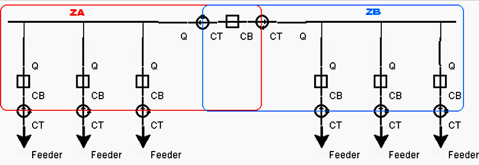
In practice there are two different solutions for bus section or bus coupler bay layout. First solution is with two sets of main CTs, which are located on both sides of the circuit breaker, as shown in Figure 11.
Two differential zones overlap across the bus-section or bus-coupler circuit breaker. No special considerations within busbar protection scheme are then necessary for this type of stations.
Figure 11 – Two Busbars with 2 CTs Tie
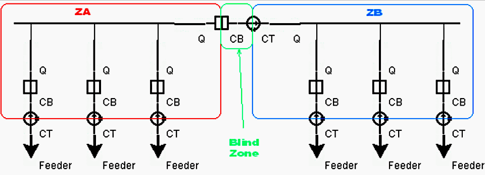
Due to the high cost of the HV current transformer often only one current transformer is available in bus-section or bus-coupler bay. This is a solution shown in Figure 12.
For this type of solution just one main CT is located on only one side of the circuit breaker. Thus, there is no zone overlapping across the section/coupler circuit breaker as shown in Figure 12.
For an internal fault in the dead zone, the differential zone ZA will unnecessarily operate and open the bus section breaker and all other feeder breakers associated with it. Nevertheless the fault will still exists on other busbar section, but is outside the current transformer in the bus section bay and hence outside the zone ZB (i.e. it is external fault for zone ZB). Similar problem will also exist if section/coupler circuit breaker was open before the internal fault in the dead zone.
Therefore, the busbar protection scheme does not protect the complete busbar.
The open contact of the section/coupler circuit breaker is normally used. However, the timing of this auxiliary contact is very important. Please note that this auxiliary contact initiating CT disconnection shall be a type which closes as soon as the main breaker contacts leave the open position. It shall not be a type which closes when the main breaker contacts reach the closed position. This solution requires good CB maintenance and might experience problems during the life time of the circuit breaker.
Figure 12 – Two Busbars with 1 CT Tie
Using external relays and this solution does not depend on contact timing between the main contacts and auxiliary contact of the breaker. This will disconnect the section/coupler CTs after about 150ms from the moment of opening of the section/coupler CB.
Nevertheless this time delay is absolutely necessary in order to prevent racing between the opening of the main breaker contact and disconnection of the CT from the differential zones.
This facility will improve the performance of the busbar protection scheme when one CT is located on only one side of the bus-section/bus-coupler circuit breaker.
Suggested Course – Mastering Power Substations: Electrical Equipment, Busbar Schemes and Relay Protection
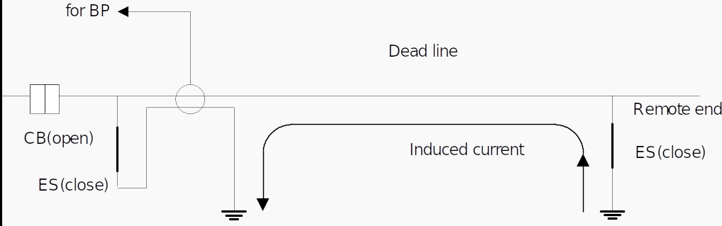
3.7 CT Location for Cable Outlet or Earthing Switch for Line
Normally earthing switch (ES), which connects the conductor to earth for safety of dead line, is located line side of CT location. But often, ES is located bus side of CT location because of primary equipment configuration.
And then in busbar protection, consideration issue against induced current flowing into ES earthing circuit is as following;
- ES earthing conductor is passed through the CT as shown in Figure 14 for cancellation of induced current.
- In case of digital relay, reading ES condition and the relay controls CT secondary output to zero.
- In cable sheath earthing, same phenomena should be considered.
Figure 13 – Solution for Busbar Protection against the Case of ES Located Line Side of CT
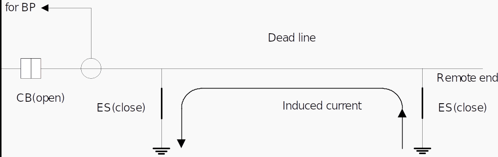
Figure 14 – Solution for Busbar Protection against the Case of ES Located Bus Side of CT
4. Attachment (PDF): Guidelines to Protection Of Synchronous Generators and Induction Generators
Download: Guidelines to Protection Of Synchronous Generators and Induction Generators (for premium members only):
Sources:
- Protection Relay Coordination by Cigre
- Construction and operational practices for EHV substations and lines by APTRANSCO
Related electrical guides & articles


Edvard Csanyi
Hi, I'm an electrical engineer, programmer and founder of EEP - Electrical Engineering Portal. I worked twelve years at Schneider Electric in the position of technical support for low- and medium-voltage projects and the design of busbar trunking systems.I'm highly specialized in the design of LV/MV switchgear and low-voltage, high-power busbar trunking (<6300A) in substations, commercial buildings and industry facilities. I'm also a professional in AutoCAD programming.
Profile: Edvard Csanyi
