
Estimated Study Time: 25 minutes
Old Substation in Five Years? Really?
Technology development has gone mad. Everything is automated, what’s needed and what’s not needed, and that’s definitely not good. Substation equipment, especially secondary systems, becomes obsolete and hard to maintain in a very short time. The main question is how to approach substation design, how much new technology to implement, and how it will be maintained after 5 years.
 Top Issues that Seriously Worry Substation Designers
Power substations must be carefully designed, constructed, and operated to fulfill customer requirements at the minimal cost consistent with the required level of service. The conventional system may comprise substations for voltage transformation, sectionalizing, distribution, and metering many times between generation and utilization, so there are thousands of tiny important details.
When designing power substations, engineers MUST think about the future, both now and in the far future. In order to provide clients with sufficient service and ensure the physical and financial integrity of electrical systems, it is crucial to make plans in a timely manner.
Detailed in the long-term plan are the needs of a substation for both its immediate and distant future use. When you’re planning the first layout, keep the end goals in mind. Find out what provisions are required for ease of addition by comparing economic factors.
In order to provide clear objectives and specifications for the substation’s design, an extensive analysis of fundamental characteristics must precede the detailed design phase.
Further factors to think about include circuit quantities, configurations, and ratings; protective relay schemes for systems and equipment; the need for specific equipment features related to surge protection; and necessary measures to prevent direct stroke.
- How System Impacts the Substation Design?
- The Impact on the Substation Single-line Diagram
- Impact on the Substation Bay
- Attachment (PDF) 🔗 Download ‘Case Study on the Power Substation Design’
1. How System Impacts the Substation Design?
Let’s draws out some general observations and conclusions on the substation design at system, single line and bay level.
When we examine the impact of the various influences on substation design, there are a number of issues which are common to many of the scenarios. This technical article considers these various impacts.
1.1 Primary Power Plant
The substation infrastructure is most likely to experience increased power transfers to meet future demands. Greater interconnection of remote generation will require utilities to increase capacity using either series compensation, HVDC or real time monitoring to enhance ratings.
Inevitably, as equipment is pushed harder the electromagnetic stress seen by primary equipment will increase, utilities will need to be able to assess this risk.
Adverse weather will directly impact on network security and the substation flexibility will determine the system resilience to these effects.
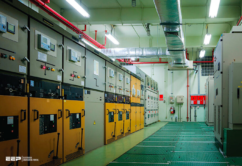
Figure 1 – Diagram of the large power plant
1.2 Secondary Systems
The application of Wide area monitoring, control and protection will become more prevalent as System Operators are faced with more dynamic networks and large scale interconnections. Embedded generation and active control within distribution networks will require significant coordination between neighbours and make traditionally separate networks much more interdependent on each other.
The communication necessary to support these developments will be central to the security and reliability of the strategy. There is likely to be a greater dependency on these systems to facilitate the changes in power networks.
Compared with the substation primary plants and instrument transformers which generally remain in-service for long life-cycles, renewed only when physically or mechanically life-expired, the secondary systems (protection and control equipment) are often changed more frequently.
The short life of protection and control equipment means that during the typical 40 year asset life of primary switchgear the secondary equipment needs to be replaced at least once and probably twice.
In addition, the replacement and maintenance of substation secondary equipment may also lead to downtime, which negatively influences the overall availability of the substation. One factor which contributes to this problem is the complex wiring required for the installation of a relay. Another possible contributing factor is relay obsolescence. If a new relay has to be installed, it may require a new configuration in order to communicate with the existing substation equipment, and this may not be possible without the use of expensive protocol converters.
Normally, outages for replacement of protection and control devices are eight weeks in duration and National Grid would like to reduce these to typically one to two weeks.
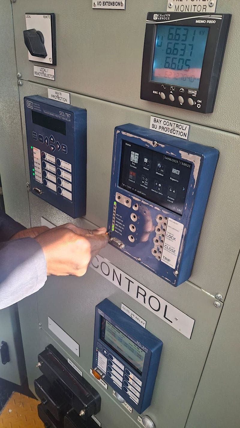
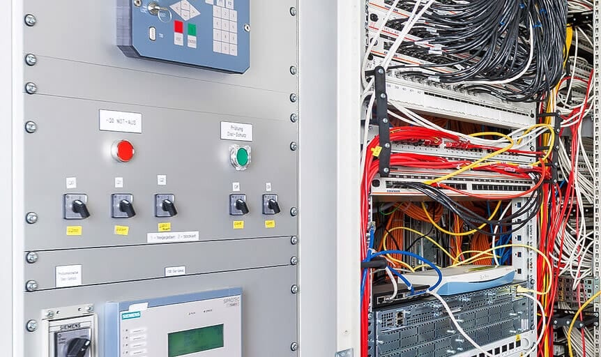
Figure 2 – Secondary equipment: Control and protection panel
One way to overcome the problem is to develop a new architecture for substation secondary systems by deploying some new technologies such as standard interface modules, process bus and IEC61850 communication protocol. The deployment of IEC61850 process bus technology will allow ongoing substation secondary equipment retrofitting (refurbishment) projects to proceed whilst limiting the duration and frequency of circuit outages, required to facilitate the work.
Once the new technology is installed, secondary equipment renewals occurring mid-life in the primary plant lifecycle can be undertaken in a safer, quicker and easier way with much reduced outages of primary systems.
As the new secondary systems transmit data of CT and VT analogue signals via the process bus, this poses no safety risks of opening CT circuits, and hence improving the safety when the protection replacement is carried out with primary circuit in service.
Interesting Study – Applying directional overcurrent relays in ground fault protection of transmission lines
Applying directional overcurrent relays in ground fault protection of transmission lines
2. The Impact on the Substation-single Line Diagram
If we look at the effect upon the single line diagram (SLD) of the substation then one of the immediate effects may be the short circuit rating required for the plant within the substation. Depending upon the device being connected this may require an increase in short circuit level or in some cases (fault current limiters) may enable simplification of the SLD by allowing greater bussing of equipment without too many sections.
The increase in harmonics on the network may give rise to a greater need for filters, either passive or active, however most transmission applications should be specified to reduce or, at least, not worsen system harmonics.
This is particularly important for electronic components, which have a very low tolerance to overvoltages.
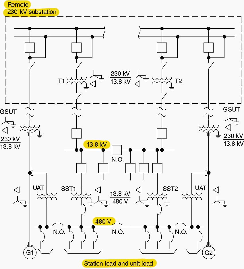
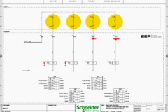
Figure 3 – Single-line diagram

2.1 Substation Configuration
The reliability and maintenance impact of new switchgear should encourage utilities to examine new running arrangements. Much longer intervals between corrective maintenance could lead to different strategies such as replace and maintain off line, rather than in situ maintenance.
For substations incorporating new technologies consideration needs to be given to the operation and running arrangement when the device has to be disconnected for maintenance or under fault conditions.
The utility will need to consider the relative cost of getting outages in the future against spare switchgear, so that rapid replacement and offline maintenance can be employed. Any element of wide area protection will also need to coordinate with these changes.
As Substation Life cycle costing becomes a more accepted method for design selection then different single line diagrams may be considered.
Further Study – Guidelines for HV substation designers to properly analyze, size and select equipment
Guidelines for HV substation designers to properly analyze, size and select equipment
3. Impact on the Substation Bay
Whatever new functionality is employed to affect system level attributes such as fault level, power flow, etc., it is invariably going to have a significant impact at the bay level.
3.1 Physical Environment
Once the substation configuration is defined, detailed design can take place to specify aspects of the substation and equipment. Space is an obvious limitation in most substations where new equipment needs to be installed. The space requirements need to consider the connectivity required with other plant items, the required electrical clearances, clearance required for electromagnetic effects, access for initial installation and maintenance.
The impact on civil works may include oil containment and fire requirements if the new devices introduce oil immersed transformers and if air cored reactors are present care has to be taken with the reinforcing bar arrangements, structures and earthing to avoid heating from closed loops.
Substation marshalling must be designed to ensure immunity to interference generated from any new applications installed in the substation which may induce transients into site cabling. Use if optical fibre will help to alleviate this problem special care is needed in the design of the earthing system, to ensure safety whilst avoiding interference into control circuits and avoiding large circulating currents from flowing due to electromagnetic induction.
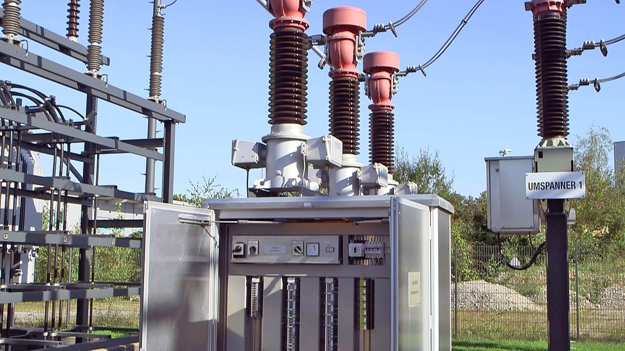
Figure 4 – Marshalling box of current transformers
Audible noise can have a significant effect on the equipment specification and subsequent testing. At the design stage the various options should be investigated such as indoor build, location or operational modes before writing very onerous equipment specifications.
A directive on EMC regarding substations as fixed installations will require the designer to consider any effects more critically since the substation is now seen a source and will need to demonstrate compliance with the standards.
Interesting Reading – Why We Still Ignore Intentional Destructive Electromagnetic Threats to Power Systems
Why We Still Ignore Intentional Destructive Electromagnetic Threats to Power Systems
3.2 Impact on Substation Equipment
There is a move towards modularity and design standardisation in an effort to reduce costs. This does mean utility specific adaptations are more difficult to make and traditional utility procedures may require review.
3.2.1 Primary Equipment
On going SF6 gas containment and tightness is a major concern among utilities, lifecycle factors need to be addressed at the specification and installation stage to ensure the desired objective of zero leakage can be reasonable achieved. Any new switchgear, especially at transmission will require SF6 gas handling, this will require training and certification under new EU regulations.
Utilities will need to specify current transformers and voltage transformers with a view to meeting future digital protection and control needs.
Worth Studying – Voltage and current measurement in modern digital high voltage substations
Voltage and current measurement in modern digital high voltage substations
3.2.2 Challenges in Upgrading Substation Automation
Substation automation will experience the greater change as interfacing new to old legacy wiring, the transfer to powered relays and isolation from the instrument transformer secondary (high impedance). There will also be a high degree of technology obsolescence.
Secondary asset replacement occurs more frequently and switchgear interfacing is proving to one of the most complex challenges. The fact that the secondary wiring may need to be changed a couple of times during the life of switchgear results in long outages to facilitate the replacement.
IEC 62271-3 aims to address some of the issues facing primary and secondary integration. Therefore in order to facilitate faster secondary asset replacement additional costs may need to be incurred at the primary asset investment stage.
Figure 5 – Digital protection panel: IEC 61850 communications
The implementation of IEC 61850 is underway and utilities need to develop their application requirements and the associated interfaces to any system management tools.
As utilities move from copper multi-core to fibre based marshalling systems, this forces the utility to establish standard termination and data protocols. Utilities need to develop their own IEC 61850 configuration requirements. New tools and training will be necessary to configure multifunctional protection ‘black boxes’ safely and reliably.
As more functionality is incorporated into equipment or Wide area systems are developed, the testing according to existing standards may require some interpretation and development, both in the factory acceptance tests and more importantly at final commissioning.
Upgrade Example – Behind upgrading the 50+ years old 132/11 kV substation
3.2.3 Auxiliary Equipment
Most of the new functionality will increase the pressure on auxiliary systems. The steady state loading is increasing and dependency on the DC supply is becoming more important than ever.
Additional AC supplies will be required for cooling of components, additional DC supplies for the control and protection. The protection design needs to consider the particular requirements of the new types of device and also the impact these devices may have upon the performance of existing system protections such as distance relays.
Interlocking may be required for both operational and safety reasons.
Further Study – Auxiliary DC power system used for fault detection, trip coils and remote operation
Auxiliary DC power system used for fault detection, trip coils and remote operation
3.3 Substation Operations
One of the common requirements for most of these new functionalities is that existing maintenance strategies may need to be reviewed. In many cases this may require procedural changes, however in a number of cases specific strategies will be required. This may result in training for substation staff or alternatively service agreements with the supplier. In both cases the costs can be large whether it is in terms of contracts or substation resource tied up in training.
Where diagnostic tools are employed such as condition monitoring or analysis provision for maintenance or calibration of these services will need to be made (exchanging one maintenance intensive system for another), albeit the latter does not tend to incur outages.
The manner in which condition monitoring is employed will enable the utility to optimise its maintenance and asset replacement strategies. The utility will need to concentrate on how the information is used within the organisation to maximise any benefit, liberal application of condition monitoring without a good input into the maintenance and asset management decision making tools will be ineffective.
Important Reading – Substation Safety and Switching Rules You MUST Follow
4. Conclusions
Engineers employed in substation design must adopt different strategies to manage change on the system, the article has only mentioned technology biased solutions, not operational or commercial alternatives. However, business and commercial processes will impact on the choice of solution employed. Conversely, behind commercial solutions there might be a need for better technical definitions concerning equipment interfaces, removable containers, post delivery support etc.
The transmission and distribution industry is by its very role conservative, which is reflected in the vintage of installed equipment and the adoption of traditional technologies and architecture.
Some of the key issues which can be drawn from the work are:
Key Issue #1
In most cases some form of Life-Cycle Costing is required to identify the optimal solution for the utility. Depending on the value utilities place on key issues such as operation and maintenance, this will affect the suitability of different solutions.
Good Reading – The life of a power substation project: Design, construction, erection and commissioning
The life of a power substation project: Design, construction, erection and commissioning
Key Issue #2
Substation designers need to consider recommendations on the application of technology and not just the technical specification. This will help to ensure the desired conclusion is reached without project delay or exceeding the budget.
Key Issue #3
There is a trend towards modularity and more standardisation of solutions, which must be considered when reviewing maintenance, refurbishment and substation extension plans.
Key Issue #4
The emphasis on maintenance is changing from intrusive testing to diagnostics and monitoring. This is moving the volume of work from the substation to the office. This strategy however requires the monitoring equipment to be more reliable than the switchgear.
Unfortunately this is not the case, so a lot of time is spent investigating the monitoring system.
Key Issue #5
New resource and skill sets are necessary (software programming and telecoms) to enable the End users to maximise the benefit from modern technology. However this must be combined with experience from the past.
Good reading – Technical Documentation for a Turnkey Substation
Key Issue #6
Detailed and bespoke engineering is necessary when interfacing between different vintages of equipment. This will impact on resource, system access and commissioning programmes.
Key Issue #7
Substation automation is very much concerned now with managing technology obsolescence and software version control. The scope of the protection engineer is broadening.
Suggested Course – The Power Substation Fundamentals Course: Theory, Equipment, Earthing, and Design
5. Attachment (PDF): Case Study on the Power Substation Design
Download: Case Study on the Power Substation Design (for premium members only):
References:
- The impact of new functionalities on substation design by Working Group B3.01
Related electrical guides & articles


Edvard Csanyi
Hi, I'm an electrical engineer, programmer and founder of EEP - Electrical Engineering Portal. I worked twelve years at Schneider Electric in the position of technical support for low- and medium-voltage projects and the design of busbar trunking systems.I'm highly specialized in the design of LV/MV switchgear and low-voltage, high-power busbar trunking (<6300A) in substations, commercial buildings and industry facilities. I'm also a professional in AutoCAD programming.
Profile: Edvard Csanyi

Established new 33/11 kv sub station
Thank you very much for send to my Email some useful articles in web “Electrical Engineering-Portal.com” for your details explanation about Design of Substation.