
Estimated Study Time: 13 minutes
Power transformers
Transformers used in power substations or a power system could be a bank of three single-phase transformers connected in either star/delta or star/star etc., or could be a single three-phase transformer with a single core. Normally for large capacity transformers, a three-phase transformer is used for the following reasons. It is lighter and cheaper, occupies less space, and is more efficient.
 Transformer connections you are not allowed to forget
The only disadvantage is that anything that affects the winding of one phase will affect the others also whereas in single-phase transformers this is not so, as one transformer can be replaced and the operation can be continued.
The magnetic circuit of a three-phase core type transformer (Figure 1) is somewhat unbalanced, central limb having less reluctance than the outer two limbs, even though the unbalancing is not appreciable.
For all practical purposes, the flux is the same in all parts of the magnetic circuit and the cross-section of the yoke and the limbs should be the same in order to have uniform flux density everywhere.

The shell-type construction as in Figure 2, with the direction of the winding the same in all three of the phases, brings in unbalancing in the flux distribution in all the limbs.

In part B of the circuit, the net flux is the phasor difference of fluxes due to phase R and Y which are equal in magnitude and displaced in phase by 120° i.e., the net flux in part B is (√3/2)×φ where φ is the flux due to each phase.
Similar is the case with part C of the circuit whereas the flux in the outer limbs is φ/2.
It is clear from Figure 3 that each phase of the shell-type transformer has an independent magnetic circuit. Therefore, if for certain reasons, (a fault) one of the windings is disabled and is removed from the circuit the remaining two windings can be operated in an open delta.

Under this condition, it is preferred to short circuit both the primary and secondary of the disabled phase so that any stray flux that may find its way into its circuit from the other two circuits is reduced to a small value. In the core type of construction, the magnetic circuits are not independent and this kind of short-circuiting of one of the phases is not done.
The type of connections for the 3-phase operation of transformers normally used is delta-star, star-delta, and delta-delta.
The delta winding is used as primary, as the generated voltage is small and the current to be handled is large. This is because the phase voltage is the same as the line to line voltage and the phase current is equal to line current divided by √3.
The grounding of the neutral of the secondary of a delta-star transformer does not introduce any problem because of the third harmonic, as the third harmonic component of the exciting current can flow in the primary delta winding.
When star-delta transformer is used as a step-down transformer, the triple harmonic component of exciting current can’t flow in the primary winding but it appears in the delta secondary winding. In other words, the main winding takes the place of the tertiary winding.
It is, therefore, always preferrable to have at least one delta connected winding in a three phase transformer, which will eliminate the third harmonic current in the external circuit and thus will avoid the interference of power lines with the communication networks.
It is to be noted that if the flux in a transformer magnetic circuit is sinusoidal, the exciting current must contain a third harmonic component.
However, if because of transformer connections or system connections, this current can’t flow, the flux will contain a third harmonic component which will induce third harmonic voltages in the transformer windings. These voltages vary between 5% to 50% of fundamental frequency voltages depending upon the type of transformer used whether core type or shell type respectively.
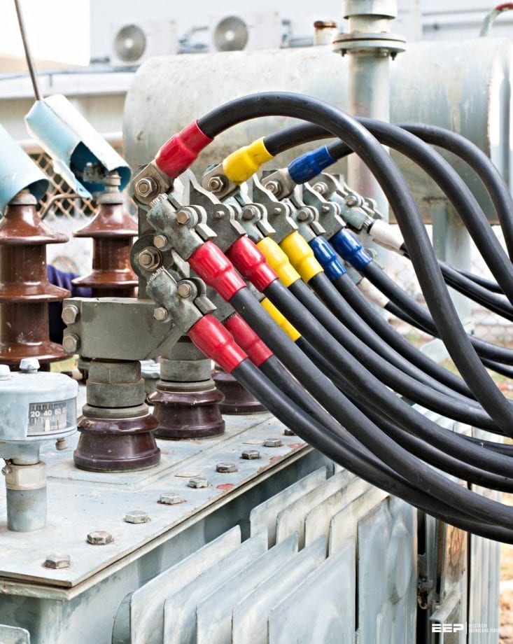
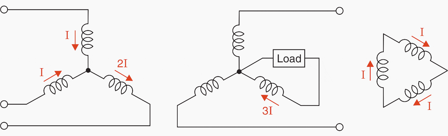
With star-star connections, the following systems (Figure 4, 5, 6, and 7) are considered for clear understanding:

In Figure 4 as the third harmonic component of current does not find a path, a third harmonic component of voltage will, therefore, be present in the line to neutral voltages even though across lines the third harmonic voltage is absent.
In Figure 5 the third harmonic component of currents do find a path and hence third harmonic component of voltages are absent.
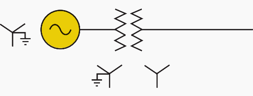
In Figures 6 and 7 because of the presence of delta winding, the delta connection provides a path for the third harmonic currents required to eliminate the third harmonic voltages.
In Figure 6, no third harmonic current will flow in the lines of the system whereas in Figure 7 the flow will depend upon the relative magnitudes of the impedances of the system and the delta winding.
However, the current is usually small and does not cause much problem with the communication networks.

In above Figure 4, the third harmonic voltages can be suppressed by providing a third winding connected in the delta. This winding is known as tertiary winding. The e.m.fs of fundamental frequency induced in these windings will be 120° apart and will, therefore, balance, but the induced e.m.fs of triple frequency will be in time phase around the closed circuit and the resultant third harmonic current will supply the magnetizing component that cannot flow in the primaries.
With a star-star connection, there is instability of the neutral because of the unbalance loading condition. The potential of the physical neutral is generally at some point other than the geometric center of the voltage triangle and is greatly affected by the characteristics of the load.
The use of tertiary along with star-star connection makes it possible to have single-phase loading of the secondary of the transformer even though the primary neutral is isolated.
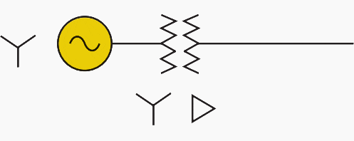
Refer to Figure 8 below.
Single-phase loading in Figure 8 is not possible as this will require current in phase Y of primary and hence the current in R and B of the same winding. Since there are no opposing ampere-turns of the secondary winding in phases R and B, therefore, no current can flow in Y of the primary winding and hence in Y of the secondary winding.
Now, if the tertiary winding is added as in Figure 9 it can be seen that the single-phase loading to the same transformer is possible.
It is to be noted here that whereas the zero sequence current and third harmonic currents resemble in some aspects they differ in the sense that whereas the flow of zero sequence currents in a circuit requires ampere-turns balancing, the flow of the third harmonic currents does not require the condition of balancing ampere-turns.
Parallel Operation of 3-phase Transformers
It is quite evident that if two transformers are star-star connected having the same ratio of transformation will operate in parallel satisfactorily as the phasor diagram of primary and secondary voltages superpose directly.
If the Line-to-Line voltages of two transformers with star-star and delta-delta connections are the same, they can operate in parallel satisfactorily as the phasor diagram of primary and secondary voltages likewise coincide.
Finally, let us consider the case when one transformer is star-delta connected and the other delta-star connected, both designed for the same line voltage on the primary and secondary sides.
The normal connections of star-delta and delta-star, transformers along with the phasor diagram are shown in Figures 10 and 11.

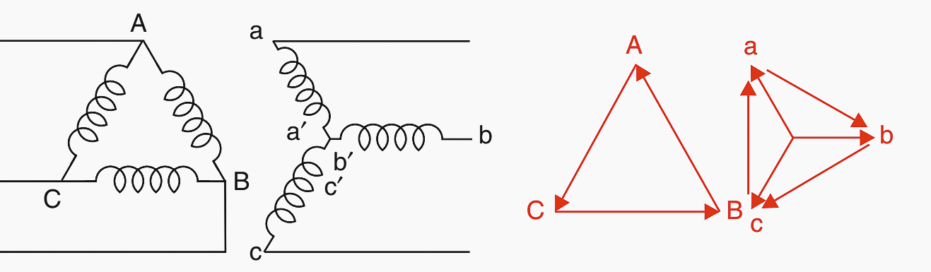
Comparing the secondary winding phasor diagrams of both the transformers, it is seen that the line voltages are not in phase, therefore, this will result in a virtual short circuit of the windings.
The two voltages can be brought in phase with each other by interchanging two phases of the primary winding and then reversing the terminals (starts and finishes) of all three primary windings as shown in Figure 12 and now the two sets of transformers can be operated in parallel.

Source: Electrical power systems by C. L. WADHWA
Related electrical guides & articles


Edvard Csanyi
Hi, I'm an electrical engineer, programmer and founder of EEP - Electrical Engineering Portal. I worked twelve years at Schneider Electric in the position of technical support for low- and medium-voltage projects and the design of busbar trunking systems.I'm highly specialized in the design of LV/MV switchgear and low-voltage, high-power busbar trunking (<6300A) in substations, commercial buildings and industry facilities. I'm also a professional in AutoCAD programming.
Profile: Edvard Csanyi

“Star-Star connections are normally not considered. The delta-star and star-delta connections are well suited to transformers in high voltage systems, the delta-star connection being used for stepping up the voltage and the star-delta for stepping down. Star connection is used for high voltages as then the phase voltage is equal to the line voltage divided by √3 and thus the windings can be insulated for lower voltages thereby the cost of providing insulation is reduced.”
I have different opinion on above paragraph for the benefit of new comers and freshers in the Industry. Star-Star are used quite frequently in Receiving Substations. They can be in the form of Power Transformer( 2 winding Trafo) or Auto Transformer. This is another matter that, either way, they may also have Tertiary Winding which will be Connected in Delta. Both High Voltage side and Intermediate Voltage side are in star. e.g. a Typical 400/220kV Auto Transformer with Delta Tertiary at 33kV (YNa0d11).
Delta Star is mostly used at Medium Voltage level e.g. 33/11kV as well at distribution voltage level of 11/0.4kV e.g. If you are talking of stepping up in the sense of Generator Step Up Trafo, then one most say it is Star Delta Transformer as in Transformer we always need to mention HV winding side connection first and in GSUT, HV side is Star Connected and LV side is Delta Connected. Only information about reduced insulation requirement makes sense. Rest all is totally confusing.
Good one
THIS EEP PORTAL HAS BEEN SO USEFUL GUIDES TO MANY OF US
Very useful information is available at EEP.
Excelente información técnica
Ur portal is good and much helpfull for us
THANKS FOR SHARING!
I really like this, and I may like to work with you people, am a Electrical Electronic Engineer, am an ND holder
Why is it necessary to separate mv from Lv earthing of transformer
Thank u so much for your teaching
Very helpful site but more explanations on other conections
This is a good one. It’s educative.
Dear Edvard,
In Malysia, transformer secondary star point neutral (Figure 7 in your article) is always grounded separately and independently through an insulated cable. The metallic frame is separately grounded through bare copper tape uninsulated. How is the star point ground cable size determined? PSCC? Thank you.
Best wishes
KIm Chuan NEOH
Very useful reference. Thank you very much.
Great article. Thank you.
Your information is very much helpful