
Transformer connections
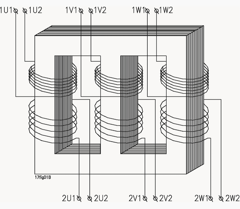
In theory a three-phase transformer works like three separate single-phase transformers with shared limbs in which the magnetic circuit for the outer limbs is longer than for the centre limb.
 Three-phase transformer connections and vector groups for beginners (photo credit: postmapostma.co.za)
The voltage transformation is determined by the ratio between the number of turns on the primary and secondary sides assuming what are known as even connections, Yy, Dd and Zz.
In the three-phase transformer we can change the transformation by going from star to delta connection. This gives us mixed connections. In the case of mixed connections the ratio between the main voltages on the primary and secondary sides is not equal to the ratio between the number of turns
Star, delta and zigzag connections
Three-phase transformers can have their windings connected in various ways: star, delta or zigzag connection.The connection type must be specified on the transformer’s rating plate.
Star, delta or zigzag connection is indicated by the letters Y, D and Z for the side with the highest voltage and y, d and z for the side with the lowest voltage. If the neutral point is connected to separate terminals, the code should be YN or ZN for the high voltage side and yn or zn for the low voltage side.
Common to all the connection types is that the transformer’s phase terminals are marked 1U, 1V and 1W on the high voltage side and 2U, 2V and 2W on the low voltage side. Any connection point which represents the windings’ neutral point is marked 1 N or 2N.
Let’s discuss about three most common transformer connections:
Star connection
In the case of star connection the three windings are connected together at their end points.The connection point represents the windings’ neutral point. Star connection is indicated by Y on the high voltage side and y on the low voltage side.
USAGE: This connection type is used for both low and high voltages and for low currents.

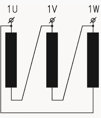
Delta connection
In the case of the ends of the windings are connected together as shown in the diagram. We can see that both the ends are connected together. Delta connection is indicated by D or d.
USAGE: This connection type is used mainly for high rated currents and low voltages.
Zigzag connection
Each phase consists of two equal windings on unequal limbs. There will therefore be parts of two phases on each limb, with one winding on each limb being connected together at the end points. Zigzag connection is indicated by Z or z. This connection type requires 15.5% more windings than star or delta connection, resulting in a larger and more expensive transformer.
USAGE: It is mainly used where load unbalance can occur between the phases and neutral.

Vector groups
The connection of all the windings in a three-phase transformer is indicated by a vector group symbol. This symbol indicates the winding connections and their relative phase displacement by means of a numerical index (e.g. Dny11).
The numerical index of the vector group comes from the clock hour gure the phase voltage hand (2U) is at when the phase voltage hand of the high voltage winding (1U) is at 12 o’clock. The system’s phase sequence should be 1U, IV, 1W, or R, S and T.
The following are the most common three-phase connections: Dd0, Dyn5, Dyn11, Yyn0, Yd1, Yd11, Dz0, Yz1 and Yz11.
Dd0

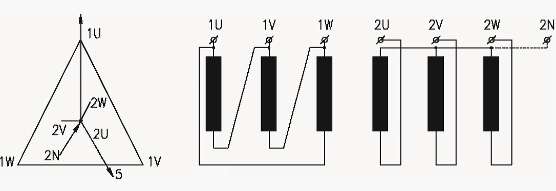
Dyn5
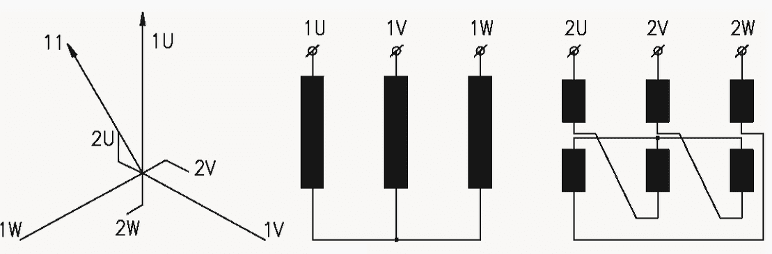
Dyn11

Yyn0

Yd1

Yd11

Dz0

Yz1

Yz11
Reference // The three-phase transformer by Noratel


I have a 3phase 480v to 240/120v 75kva transformer,I believe it’s a delta,it has x1,x2,x3,x6,is the x6 for muetral connection? Looking for verification.thanks for the help
I have a very old transformer rating plate that gives the vector at Dd165.
What will this vector grouping be in modern IEC notation?
Testing procedure of Dzn0 vector group.
Pls I have three phase transformer for sail. My location is warri Delta state
Dear all,
If we have transformer Ynd5 it is possible with reconnecting primary phases and/or secondary phases to receive transformer Ynd11?
Thanks !
I would like to know why is it necessary to have a phase shift of 30 degree for Dyn5. What is the purpose of phase shift ?
I want more to learn about electrical system