There is no ‘ideal’ transformer
Since no transformer is truly an “ideal” transformer, each will incur a certain amount of energy loss, mainly that which is converted to heat. Methods of removing this heat can depend on the application, the size of the unit, and the amount of heat that needs to be dissipated.

The insulating medium inside a transformer, usually oil, serves multiple purposes, first to act as an insulator, and second to provide a good medium through which to remove the heat.
The windings and core are the primary sources of heat, although internal metallic structures can act as a heat source as well. It is imperative to have proper cooling ducts and passages in the proximity of the heat sources through which the cooling medium can flow so that the heat can be effectively removed from the transformer.

The natural circulation of oil through a transformer through convection has been referred to as a “thermosiphon” effect. The heat is carried by the insulating medium until it is transferred through the transformer tank wall to the external environment.
Radiators, typically detachable, provide an increase in the surface area available for heat transfer by convection without increasing the size of the tank. In smaller transformers, integral tubular sides or fins are used to provide this increase in surface area.
Larger transformers that cannot be effectively cooled using radiators and fans rely on pumps that circulate oil through the transformer and through external heat exchangers, or coolers, which can use air or water as a secondary cooling medium.
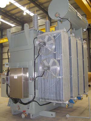 Allowing liquid to flow through the transformer windings by natural convection is identified as “nondirected flow.” In cases where pumps are used, and even some instances where only fans and radiators are being used, the liquid is often guided into and through some or all of the windings.
This is called “directed flow” in that there is some degree of control of the flow of the liquid through the windings.
The difference between directed and nondirected flow through the winding in regard to winding arrangement will be further discussed with the description of winding types. The use of auxiliary equipment such as fans and pumps with coolers, called forced circulation, increases the cooling and thereby the rating of the transformer without increasing the unit’s physical size. Ratings are determined based on the temperature of the unit as it coordinates with the cooling equipment that is operating.
Usually, a transformer will have multiple ratings corresponding to multiple stages of cooling, as the supplemental cooling equipment can be set to run only at increased loads. Methods of cooling for liquid-immersed transformers have been arranged into cooling classes identified by a four-letter designation as follows:
Four letter cooling classes
| 1 | 2 | 3 | 4 | |||
| medium | mechanism | medium | mechanism | |||
| Internal | External | |||||
Table 1 – Cooling Class Letter Description
| Letter | Description | ||
| Internal | First Letter | O | Liquid with flash point less than or equal to 300°C |
| K | Liquid with flash point greater than 300°C | ||
| L | Liquid with no measurable flash point | ||
| Second Letter (Cooling mechanism) | N | Natural convection through cooling equipment and windings | |
| F | Forced circulation through cooling equipment, natural convection in windings | ||
| D | Forced circulation through cooling equipment, directed flow in man windings | ||
| External | Third letter (Cooling medium) | A | Air |
| W | Water | ||
| Fourth letter (Cooling medium) | N | Natural convection | |
| F | Forced circulation |
Table 1 lists the code letters that are used to make up the four-letter designation. This system of identification has come about through standardization between different international standards organizations and represents a change from what has traditionally been used in the U.S. Where OA classified a transformer as liquid-immersed self-cooled in the past, it is now designated by the new system as ONAN. Similarly, the previous FA classification is now identified as ONAF.
FOA could be OFAF or ODAF, depending on whether directed oil flow is employed or not. In some cases, there are transformers with directed flow in windings without forced circulation through cooling equipment.
An example of multiple ratings would be ONAN/ONAF/ONAF, where the transformer has a base rating where it is cooled by natural convection and two supplemental ratings where groups of fans are turned on to provide additional cooling so that the transformer will be capable of supplying additional kVA. This rating would have been designated OA/FA/FA per past standards.




What is differrnt between class A and class B for oil type transformers and which one suitable for African hot area country.
What is mean by man windings mentioned in the second letter D???
Many times dissipating heat at transformer location is not desirable. In that case How about using Plate Heat Exchanger? Using a pump to circulate transformer tank oil in one side of PHE & another pump to circulate cooling oil of same grade as transformer oil in other side of PHE. Take the cooling oil away in a radiator. This radiator can be air cooled with fan or without fan.
Since both media are same grade (dielectric), contamination is ruled out.
Thanks
Can a transformer that is rated ODAF be run without the fans and pumps running? Can the fans and pumps be started when the winding temperature controls turn them on?
Forced Circulation through cooling equipment, *direct* flow in main winding
If the transformer is ODAF, then the pumps have to run continuously (maybe not all if operated in parallel) and the fans can be managed by temperature control. To be considered that there is a hidden concern when reducing the number of operated pumps – winding over oil gradient is higher than predicted by WTI on the base of factory temperature rise test. WTI will be underestimating real winding temperature and thus delay the start of extra pumps and fans.
In an emergency situation, such transformer is able to work without both, pumps and fans, but much shorter time comparing to OFAF transformer. This time is subject to calculations, depends on the initial transformer temperature and load.
I currently have several transformers that are running hot. I would like to add fans to their radiators, but I do not know how many I need, and in what configuration. If you ask the manufacturer, they will tell you to cover the entire radiator with fans. When you look at other transformers in the facility, you will see as many different cooling fan arrangements, as you will see different sizes of transformers. How do I know which arrangement is optimal?
Hi Jeff
Could your kindly write an email regarding the same, we are specialists in Transformers colling systems and I would like to discuss more on the subject.
What are the drawbacks in initialing the cooling bank by detecting loading current rather than the winding temperature??
it will not consider ambient temperature…
It may happen you will start cooling when the transformer does not need it as for example is in the Arctic climate at wintertime, or cooling will not start when ambient is very high and cooling is already needed.
In some practices cooling initialization is split: the pumps are driven by the transformer load and fans by oil/winding temperature.
list for me five types of transformer cooling
Oil Natural Air Natural (ONAN)
Oil Natural Air Forced (ONAF)
Oil Forced Air Forced (OFAF)
Oil Forced Water Forced (OFWF)
Oil Natural Water Forced (ONWF)
I afraid that ONWF is impossible in practical situations type of cooling. Oil to be forced via water cooler. ODWF could be the fifth example
Got a question: Will the short circuit values be different depending on the cooling system, meaning will it be different if natural air than forced air for exmample?
Regards,
dear sir,
Tell how to choose transformer cooling fans for rated(1600,2000,12000kva)transformer..
Doesn’t the fourth letter in Table 1 represent external cooling mechanism? In the table above, it indicates cooling medium. Copy/paste error?
Great information; thanks!
Great article! Gratitude for explaining a few very complex issues in a very simple manner. Would you mind explaining the followings:-
1 Information/data about the behaviors of synthetic ester (IEC 61099) based dielectric fluid with various solid insulation’s including papers.
2-Heat dissipation /duct size adjustment for using synthetic ester- as the perception is that low viscosity oil works better and IEC 61099 fluids are viscous- require to increase the duct size or the gap between the conductors.
3-Is it possible to use synthetic ester in Capacitors.
Regards
Great article..thanks alot for this wonderful service,,
GOOD info thanks