Inter-winding faults
Similar to bus protections, transformers are protected by differential relays. Inter-winding faults (short circuits) and ground faults within power transformers can be detected by this protection scheme.

Failure to detect these faults and quickly isolate the transformer may cause serious damage to the device.
Remember that a differential relay is basically an instantaneous overcurrent relay that operates on the difference of current flowing into and out of the protected zone.
For transformers the differential protection (Figure 1) is basically the same as that for a bus but there are certain differences that we will look more closely at.
These differences are a direct result of three characteristics or a transformer:
1. A transformer has a turns ratio so the current in is not really equal to the current out. The current transformers are not likely exactly matched to the transformer turns ratio so there will always be an unbalance currentin the operating coil of a transformer differential relay.
2. Transformers require magnetising current. There will be a small current flow in the transformer primary even if the secondary is open circuited.
3. A transformer has an inrush current. There is a time period after a transformer is energized until the magnetic field in the core in alternating symmetrically. The size and the length of this inrush depends on the residual field in the core and the point in the ac cycle the transformer is re-energized.
In large transformers in might be ten or twenty times the full-load current initially and it might take several minutes to reduce to negligible values.
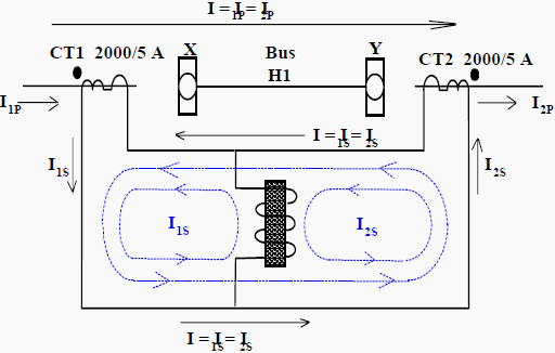
Transformer differential relays haverestraint coils as indicated in Figure 1. The value of the operate current has to be a certain set percentage higher than the current flowing in the restraint coils. For this reason transformer differential relays are said to percentage-differential relays.
Referring again to Figure 1, you will notice that when the transformer is first energized, there will not be any current flowing in CT2. The CT1 secondary current I1s flows through both the restraint and operate coils and prevents operation unless the current is very high.
The restraint coils also prevent relay operation due to tap-changes, where the ratio of transformer input to output current can continuously vary.
When transformers are first energized there is over-fluxing (saturation) of the core and the large inrush energizing current has a distorted waveform. This waveform is described as having high second harmonic content.
The transformer differential relays make use of this known fact and add in extra restraint when it detects this second harmonic. This extra feature prevents the transformer from tripping due to magnetizing current when being energized, but does not add any time delay.
Because the differential relay will not operate with load current or faults outside the protected zones (through faults), it can be set to operate at a low value of current thereby giving rapid operation when a fault occurs. There is no need to time delay the operation of the relay and therefore a fast acting type of relay can be used.
Resource: Science and Reactor Fundamentals – Electrical – CNSC Technical Training Group






Pls can you tell me that,how to resolving our problem that have diff foult on relay when we make on transformer after take 90A load ,transformer make shut down immediately
Helpfull tremendous website for engineer and electrician.
I like very much.
Please consider writing an article about all the standard transformer winding impedance measurements, their meaning/importance and how they are determined. When researching these values there appears to be some inconsistency in naming and test conventions. For instance, Positive Sequence values are found on the transformer nameplate but not zero sequence values. Depending on the manufacturer, they will also a second set of values called Inter-winding Impedance, some having negative values. Many times the numeric values of these impedances are similar and thus when incorrectly applied return reasonable results. When trying to reproduce zero sequence impedance values in the field, some manufacturer’s will you short all the phases together on a winding and others will have you leave them open. The bottom line is a confusing situation.
Thanks
Differential relay operates when an internal fault occurs in transformer then how can we say that it protects against internal faults.
Hi, it’s easy to understand the concepts. Would like to have your opinion on why we multiply 1.5 for star/wye winding and 1.732 for Delta winding when testing the pickup levels of a differential relay single phase at a time.
What could be the problem in a 45MVA 132/33kV transformer that is tripping instantly on differential and HV earth fault and all the tests conducted are OK apart from stability test.
We have done;
Mark curves
Polarity checks
Stability tests* here we have circulating current on neutral
Ratio
Turns ratio
Capacitance
Excitation
Magnetic balance
Winding resistance on all taps
Insulation tests
DGA
If you have not conducted the stability test than please conduct the same. May be the terminals of REF relay got interchanged during installation. When you conduct stability test than do check the current flowing through the neutral that is it will add up.
how to do the stability test of differential relay
Good website for protection engineer
very informative indeed
Our site transformer core to earth internally earthed.if we removed link for core to earth also core to earth megger value only <10 k ohm.inthis condition can be energised?
Hi Edvard
thanks for your kind cooperation.
i have a simple question. in my project there is a transformer with following information:
25/4.16 kV, Dy neutral grounded with resistor (25A).
what is the minimum capacity of transformer need to have differential protection. please let me know related standard or recommendation.
Thanks indeed.
As per CBIP 295 , 3.15MVA and above differential protection is required.
Great..
thanks
Very valuable article …
Thanks
the EEP website has helped so much that have being having less problems in almost all the areas of electrical fields.switch gear maintenance has being the key area at my plant as we have reduced unnecessary breakdowns of the plant due to poor maintenance