


Estimated Study Time: 29 minutes
Differential Protection: Theory vs. Practice
The technical article provides a deep, technical analysis of the discrepancies between differential protection in theory and real-world grid relay operations. It includes customized vector graphics and schematics illustrating inrush waveforms, dual-slope restraint characteristics, internal turn-to-turn loops, CT saturation, zero-sequence trapping in delta windings, and IEC 61850 process bus architecture.
 Transformer Differential Protection: When Textbook Theory Doesn't Fit Reality
We all learned about transformer protection in college, and as far as I remember, transformer protection is presented as a paragon of logic and mathematical symmetry. The core concept and the differential protection scheme (ANSI 87T) is built upon the infallible foundation of Kirchhoff’s Current Law.
The textbook theory dictates that the sum of the currents entering a node must equal the sum of the currents leaving it. So, is it true?
The Intelligent Electronic Device (IED) calculates this difference, issues a trip command to the respective circuit breakers, and isolates the transformer to prevent catastrophic failure.
Idiff = | Σ Ιscaled | = | Ι1_sec + Ι2_sec |
If this equation were the entirety of the discipline, power system protection would be a trivial exercise. However, in the harsh, dynamic reality of the HV grid, this theory simply disintegrates. Power transformers are far from ideal piece of equipment.
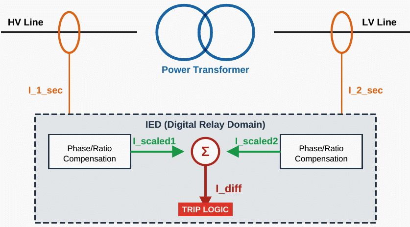
Figure 1 – Transformation of physical secondary currents (I_sec) into digital scaled currents (I_scaled) to calculate Differential Current (I_diff)
Where Differential Protection Variables are:
I1_sec and I2_sec (Secondary Currents): These are the raw, physical analog currents flowing out of the Current Transformers (CTs) on the high-voltage (1) and low-voltage (2) sides of the power transformer. They are typically scaled down by the physical CT ratio to standard nominal values (e.g., 1A or 5A) before entering the relay terminals.
Iscaled (Scaled Current): This is a purely mathematical value calculated inside the digital Intelligent Electronic Device (IED). Because the primary and secondary windings have different voltage levels, phase shifts (e.g., Delta-Wye connections), and potentially mismatched CT ratios, I1_sec and I2_sec cannot be compared directly.
The relay applies internal compensation matrices to adjust magnitude and rotate the phase angles, creating Iscaled so both sides share a common, unified mathematical baseline.
Idiff (Differential Current): The calculated vector sum of the scaled currents inside the relay. The equation is Idiff = | Iscaled1 + Iscaled2 |. Under normal load or external faults, the scaled vectors cancel each other out (Idiff ≈ 0). During an internal fault, they sum together, producing a high Idiff that triggers a trip command.
Modern protection engineers, particularly those working with advanced digital substations and complex IEC 61850 network architectures, know that managing a protection relay involves resolving the conflict between theoretical mathematics and physical reality.
The commissioning engineer is not merely balancing an equation; they are managing core physics, electrical transients, mechanical limitations, and digital logic matrices.
This article provides a deep, comprehensive exploration into the fundamental discrepancies between textbook differential theory and the practical realities of transformer protection, detailing the sophisticated mechanisms required to bridge this gap.
It relies on the IEEE C37.91 (Guide for Protecting Power Transformers) and standard manufacturer application manuals for digital transformer differential relays.
- The Inrush Phenomenon and the 2nd Harmonic Dilemma
- On-Load Tap Changers (OLTC) and the Floating Baseline
- The Turn-to-Turn Fault Blind Spot and the Autotransformer Effect
- CT Saturation: When the Messengers Fail
- Phase Shifts, Zero-Sequence Traps, and Digital Matrices
- Overexcitation (Volts/Hertz): When the Core Escapes the Windings
- The IEC 61850 Reality: Digital Substations and Network ‘Jitter’
- Summary
- Attachment (PDF) 🔗 Download ‘Calculation of CTs/VTs For 500/33 kV Power Substation’
1. The Inrush Phenomenon and the 2nd Harmonic Dilemma
The most immediate challenge to the differential principle occurs the moment a transformer is energized. According to textbook theory, a healthy transformer drawing no load should exhibit zero differential current. Reality, however, dictates that upon energization, the transformer must establish its magnetic core flux.
Because the AC voltage waveform may be applied at a zero-crossing, the core flux (which trails voltage by 90 degrees) is forced to rapidly double its peak value to maintain the mathematical relationship between voltage and flux linkage.
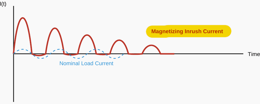
This “inrush current” can peak at 10 to 15 times the nominal full-load current of the transformer. Crucially, because this current is drawn solely from the energizing source and does not pass through to the secondary load, it appears to the differential relay as a large, one-sided internal fault.
The classical textbook solution to this problem is harmonic restraint. Fourier analysis of the asymmetrical inrush waveform reveals it is heavily distorted, containing a big DC offset and a high proportion of even harmonics, most notably the 2nd harmonic.
Figure 1 – Typical asymmetrical magnetizing inrush current waveform upon transformer energization, heavily DC-offset
Therefore, legacy relays were designed to calculate the ratio of the 2nd harmonic to the fundamental frequency.
If I2nd / I1st > 15%, the relay concludes the event is an inrush, not a fault, and blocks the trip signal.
However, reality strikes again via advances in metallurgy. Modern power transformers utilize highly efficient cold-rolled grain-oriented (CRGO) silicon steel cores designed to operate much closer to the knee-point of the saturation curve to minimize hysteresis losses. These advanced materials, combined with optimized step-lap core joint construction, alter the fundamental physics of the inrush.
When a modern transformer is energized, the resulting inrush waveform is significantly “smoother” and contains far less 2nd harmonic content, often dropping below 10% or even 7%.
Furthermore, “sympathetic inrush“, (where the energization of an adjacent parallel transformer causes a DC voltage drop that momentarily saturates the already-running transformer) can cause the healthy transformer to trip offline if the harmonic profile isn’t evaluated correctly.
Further Study – The Worst Transformer Inrush Current Occurs When…
1.1 The Newest Engineering Solution
Today’s microprocessor-based relays implement advanced Waveform Recognition algorithms. Instead of relying purely on harmonic ratios, the IED analyzes the exact shape of the Idiff waveform. Inrush currents exhibit distinct periods of zero current (flat spots) during each cycle when the core briefly exits saturation. Relays measure the duration of this gap (Gap Detection).
If the dwell time near zero exceeds a quarter-cycle (approx. 4-5 ms in a 50Hz system), the relay blocks the trip regardless of the 2nd harmonic content, bridging the gap between theory and modern metallurgical reality.
2. On-Load Tap Changers (OLTC) and the Floating Baseline
A fundamental principles of differential theory is that the input and output currents can be mathematically balanced by applying the transformer’s turns ratio. In textbook exercises, this ratio is static. In the real world, grid voltage is highly volatile. To maintain stable voltage for distribution networks or industrial facilities, high-voltage transformers are equipped with On-Load Tap Changers (OLTC).
The OLTC mechanically adds or removes physical turns from the high-voltage winding while the transformer is energized and carrying load, typically adjusting the voltage in small steps across a range of ±10% to ±20%.
Consequently, the physical turns ratio of the transformer is a moving target.
If a simple overcurrent threshold were used for the differential element, the relay would trip the moment the load current increased while the tap was at an extreme position.
Figure 2 – The Dual-Slope Percentage Restraint Characteristic designed to accommodate OLTC mismatch and CT saturation errors
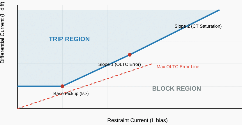
To reconcile the theory of balance with the reality of an active OLTC, relay engineers must implement a Percentage Restraint (Bias) Characteristic, commonly known as a dual-slope curve. Instead of a fixed trip threshold, the relay continuously calculates a Restraint Current (I = ( | I1 | + | I2 |) / 2), which represents the bias total through-current.
The required differential current to cause a trip (Idiff_trip) is no longer a static number, because it increases proportionally with the through-current. The gradient of the first slope (Slope 1) is explicitly set by the commissioning engineer to be greater than the maximum possible error introduced by the OLTC at its extreme tap positions (plus inherent CT ratio errors).
While this elegantly solves the nuisance tripping problem, it reveals a harsh trade-off:
To maintain stability under heavy load with tapped windings, the relay’s sensitivity to genuine, low-level internal faults is inherently degraded.
Learn more – 132/33kV, 31.5MVA Transformer Protection Schematics (PDF)
3. The Turn-to-Turn Fault Blind Spot and the Autotransformer Effect
Perhaps the most dangerous divergence between electrical theory and physical reality lies in the detection of early-stage turn-to-turn faults. In the idealized differential theory, any short circuit within the transformer zone will change the primary-secondary current balance, triggering an instantaneous trip.
The assumption is that faults are big events involving phase-to-phase or phase-to-ground arcing.
Related electrical guides & articles






Edvard Csanyi
Hi, I'm an electrical engineer, programmer and founder of EEP - Electrical Engineering Portal. I worked twelve years at Schneider Electric in the position of technical support for low- and medium-voltage projects and the design of busbar trunking systems.I'm highly specialized in the design of LV/MV switchgear and low-voltage, high-power busbar trunking (<6300A) in substations, commercial buildings and industry facilities. I'm also a professional in AutoCAD programming.
Profile: Edvard Csanyi