
Estimated Study Time: 14 minutes
Transformer exterior inspection
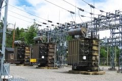
Periodic transformer exterior inspection (visual) reveals important condition information. For example, valves positioned incorrectly, plugged radiators, stuck temperature indicator and level gauges, and noisy oil pumps or fans. Oil leaks can often be seen which indicate a potential for oil contamination, loss of insulation, or environmental problems.
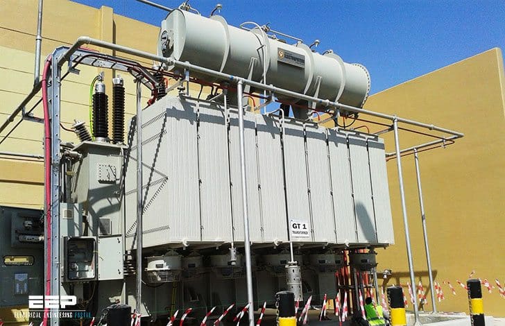 Transformer exterior inspection and tests you MUST perform (photo credit: electroputere11.files.wordpress.com)
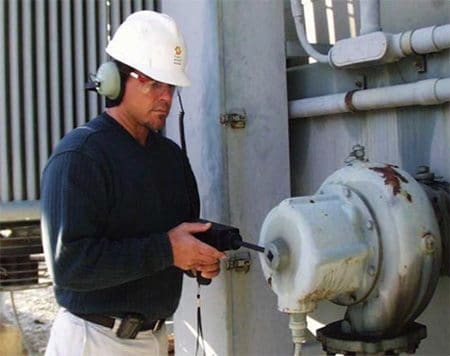
Physical inspection requires staff experienced in these techniques.
- To check:
- To perform:
- Other also important inspections
To check //
Oil leaks
Check the entire transformer for oil leaks. Leaks develop due to gaskets wearing out, ultraviolet exposure, taking a “set,” or from expansion and contraction, especially after transformers have cooled, due to thermal shrinkage of gaskets and flanges.
Many leaks can be repaired by applying an epoxy or other patch. Flange leaks may be stopped with these methods, using rubberized epoxy forced into the flange under pressure.
Experienced leak mitigation contractors whose work is guaranteed may also be employed.
Some leaks may have to be welded. Welding may be performed with oil in the transformer if an experienced, qualified, and knowledgeable welder is available. If welding with oil in the tank is the method chosen, oil samples must be taken for DGA, both before and after welding.
Welding may cause gases to appear in the DGA and it must be determined what gases are attributed to welding and which ones to transformer operation.
Go back to Transformer exterior inspection ↑
Oil pumps
If the transformer has oil pumps, check the flow indicators and pump isolation valves to ensure that oil is circulating properly.
Check oil pumps with a vibration analyzer if they develop unusual noises. Have the DGA lab check for dissolved metals in the oil and run a metal particle count for metals, if the bearings are suspect. This should be performed as soon as a bearing becomes suspect.
Bad oil pump bearings can put enough metal particles into the oil to threaten transformer insulation and cause flashover inside the tank, resulting in an explosive catastrophic failure of the transformer tank.
Go back to Transformer exterior inspection ↑
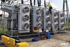
Fans and radiators
Inspect all isolation valves at the tops and bottoms of radiators to ensure they are open. Inspect cooling fans and radiators for cleanliness and fans for proper rotation. Check for dirty or damaged fan blades or partially blocked radiators.
This means that the blades are rotating in warm air after it passes through the radiator, which is much less efficient. Place a hand on the radiator opposite the fans. Air should be coming out of the radiator against your hand. Watch the blades as they rotate slowly when they are starting or stopping to determine which way they should be rotating and correct the rotation if necessary.
See IEEE 62-1995 for details. Also inspect radiators and fans with an infrared camera, see section Infrared temperature analysis.
Go back to Transformer exterior inspection ↑
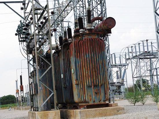
Age
Transformer age is an important factor to consider when identifying candidates for replacement or rehabilitation. Age is one indicator of remaining life and upgrade potential to current state-of-the art materials. During transformer life, structural strength and insulating properties of materials used for support and electrical insulation (especially paper) deteriorate.
Although actual service life varies widely depending on the manufacturer, design, quality of assembly, materials used, maintenance, and operating conditions, the expected life of a transformer is about 40 years.
Go back to Transformer exterior inspection ↑
To perform //
Infrared temperature analysis
Infrared analysis should be conducted annually while equipment is energized and under full load, if possible. IR analysis should also be conducted after any maintenance or testing to see if connections that were broken were re-made properly.
Also, if IR is performed during factory heat run, the results can be used as a baseline for later comparison.
Infrared for transformer tanks
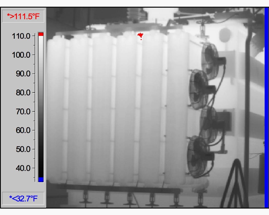
Unusually high external temperatures or unusual thermal patterns of transformer tanks indicate problems inside the transformer, such as low oil level, circulating stray currents, blocked cooling, loose shields, tap changer problems, etc. Infrared scanning and analysis is required annually for trending purposes by National Fire Protection Association 70B,
See figure 1 for a normal pattern; the red spot at the top is normal showing a “hot spot” top of B phase, about 110 degrees Fahrenheit (°F). Any departure from this pattern means a probable problem which must be investigated. An IR inspection can find over-heating conditions or incorrect thermal patterns. IR scanning and analysis requires trained staff, experienced in these techniques.
Go back to Transformer exterior inspection ↑
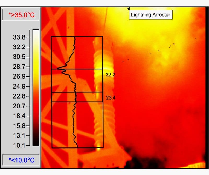
Infrared for surge arresters
Surge arresters should be included when infrared scanning energized transformers. Look for unusual thermal patterns on the surface of lightning arresters.
See the arrester IR image in figure 2 below. Note that the yellow in the top right of the image is a reflection not associated with the arrester. A temperature profile of the arrester is shown as black lines. Note the hot spot (yellow) about a third of the way down from the top.
Also compare thermal patterns to sister units or earlier scans of the same arrester. Scan all high voltage connections and compare them to nearby connections for unusual temperatures.
Go back to Transformer exterior inspection ↑
Infrared for bushings
IR scans of bushings can show low oil levels which would call for immediate de-energization and replacement. This generally means that the seal in the bushing bottom has failed, leaking oil into the transformer. The top seal has probably also failed, allowing air and up the bushing.
Remember, over 90% of bushing failures are attributed to water entrance through the top seal. Bushings commonly fail catastrophically, many times destroying the host transformer or breaker and nearby equipment and causing hazards to workers.
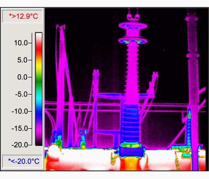
Figure 4 (below) shows low-oil level in a high voltage transformer bushing. Compare previous IR scans of the same bushing with the current scan.
Doble hot-collar testing possibly may show this problem. However, Doble tests are run infrequently, and the transformer has to be out of service, under clearance, and both primary and secondary conductors removed, while an IR scan easily can be performed at any time.
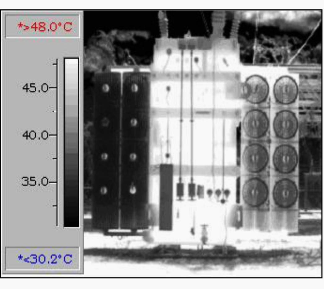
Infrared for radiators and cooling systems
Examine radiators with an IR camera and compare them with each other. A cool radiator or segment indicates that a valve is closed or the radiator or segment is plugged. The IR image (figure 4) shows that the cold left radiator section is valved off or plugged.
Remember, an increased operating temperature of only 8 to 10 °C will reduce transformer life by one-half. IR scan all cooling systems, including heat exchangers, fans, pumps, motors, etc. Check inside control panels for overloaded wiring, loose connections, and overheated relays. Look for unusual thermal patterns and compare similar equipment.
Go back to Transformer exterior inspection ↑
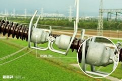
Corona Scope Scan
With the transformer energized, scan the bushings and surge arresters and all high voltage connections for unusual corona patterns. Corona should be visible only at the top of bushings and arresters, and corona at connections should be similar to sister connections. As a bushing deteriorates due to physical defects, the corona pattern will grow progressively larger.
When the corona pattern reaches a grounded surface (i.e., the tank or structure), a flashover will occur, destroying the bushing or arrester and, perhaps, the transformer. The corona scope will reveal this problem long before a flashover.
Go back to Transformer exterior inspection ↑
Other also important inspections
There are several required physical inspections that will not be covered here because they were addressed previously. Be sure to inspect the following:
- Winding temperature indicators
- Pressure relief devices
- Sudden pressure relay
- Conservator bladder
- Conservator breather and
- Bladder failure relay
Go back to Transformer exterior inspection ↑
Reference // Transformers: Basics, Maintenance, and Diagnostics by U.S. Department of the Interior Bureau of Reclamation
Related electrical guides & articles


Edvard Csanyi
Hi, I'm an electrical engineer, programmer and founder of EEP - Electrical Engineering Portal. I worked twelve years at Schneider Electric in the position of technical support for low- and medium-voltage projects and the design of busbar trunking systems.I'm highly specialized in the design of LV/MV switchgear and low-voltage, high-power busbar trunking (<6300A) in substations, commercial buildings and industry facilities. I'm also a professional in AutoCAD programming.
Profile: Edvard Csanyi

I think this is very good information for experienced and non-experienced engineers, industrial electricians, maintenance managers, technicians and people who works in related fields. It’s very practical, I could immediately use it because it is very well explained…thanks!
Hi
Mr.Edvard
Your Articles in Electrical industrial Engineering are very useful for so many persons like me.
Upload more video’s related to breakers transformers and plc based drives and about relay settings and fault analysis of different electrical equipment’s. And also about HT Drives working procedure.
Yours Sincerely
VALLURU KISHORE
Good info on Transformer Inspection.
Is it possible to test a three phase transformer for Voltage ratio and Vector using single phase voltage?
Nice..but also need which type epoxy to be applied.. kindly tell us types of putty/epoxy.So that we will procure accordingly.
I am impressed with your teachings and it have been and eye opening to me and I desire to know more but I don’t know how to get in contact with you for more information and study guides
Nice and helpful. Please, continue.