
Why is maintenance so important?
The primary purpose of transformer maintenance is to ensure the internal and external parts of the transformer and accessories are kept in good condition and “fit for purpose” and able to operate safely at all times. A secondary and equally essential purpose is to maintain a historical record of the condition of the transformer.
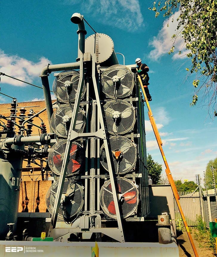 Maintenance instructions on what to do if the transformer goes down (photo credit: Wayne Sidderley via Flickr)
Transformer maintenance can be done periodically or as condition-based maintenance. The latter is usually the most economical way of doing maintenance.
Recommended maintenance is then done based on one or more of the following: inspections, analysis of oil samples, electrical measurements, test of equipment, measurement of temperatures by using a heat-sensitive camera, monitoring (off-line and/or on-line).
- Maintenance in energized condition
- Maintenance in de-energized condition
- Investigation of transformer disturbances:
- Transformer liquid and insulation
- Bushings and joints
- Off-circuit tap changer
- On-load tap-changer
- Motor drive unit
- Oil filtering unit
- Coolers
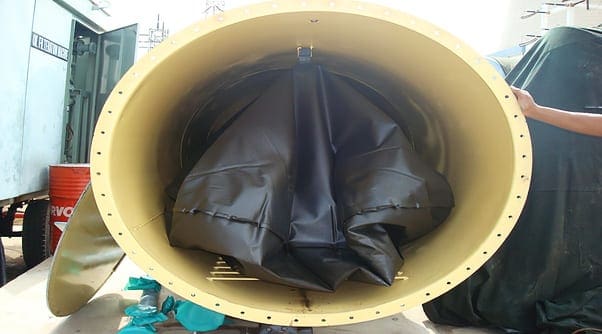
- Liquid conservator with rubber diaphragm
- Gaskets
- Dry-type transformers
- Surface protection
1. Maintenance in energized condition
For personal safety reasons, only a limited amount of maintenance activities should be performed on the transformer when it is in operation.
When necessary safety precautions have been taken the following maintenance can be done in energised condition:
- Inspection for leakages, cracks in porcelain bushings, check of auxiliary equipment etc.
- Check drying material in the dehydrating breather (conservator type only).
- Measurement of temperatures of joints, bushings etc. by using a heat-sensitive camera.
- Oil samples (conservator type only).
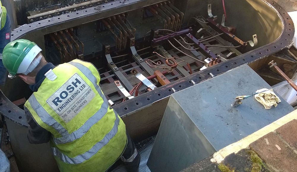
2. Maintenance in de-energized condition
Before starting maintenance work, the transformer has to be disconnected from the network and earthed. When the circuit breaker and the isolator have been opened, they shall be locked in an open position to prevent inadvertently closing during maintenance work.
Items to be considered are:
- Bushing gaskets; if leaks occur, tightening usually will help, if the gasket has lost its elasticity, it must be replaced. The reason for loss of elasticity could be excessive heating or ageing,
- Cover gaskets, valves and gaskets of the tap changer. If there are leakages, bolt tightening will often help,
- Welded joints. Leaking joints can be repaired only by welding.A skilled welder and welding instruction are required.
- Cleaning contaminated bushings (cleaning agent e.g. methylated spirit),
- Cleaning glasses on the gas relay, thermometer and liquid level indicator,
- Functional inspection and testing of applicable accessories,
- Move tap changer through all positions a few times, all types of tap changers,
- Liquid sampling from bottom drain valve for larger units as required,
- Check drying material in the dehydrating breather. (Conservator type only),
- Amend surface treatment defects,
- Oil and insulation maintenance, drying and reclaiming,
- Tap-changer maintenance,
- Inspection and maintenance on the active part should not be performed unless there are unambiguous indications of defects.
In addition, for dry-type transformers:
- Inspection and e.g. vacuum cleaning as required,
- Humidity removal,
- Tightening winding supports.
In heavily contaminated installations more frequent inspections may be needed.
3. Investigation of transformer disturbances
If, during operation, the protective equipment of the transformer gives an alarm or trips the transformer from the network, one should immediately investigate the reason for it.
Studies may reveal whether it is a question of transformer damage or some other disturbances in the system.
3.1 Fault localisation advice, dry type transformers
For dry-type transformers, see table below in addition:
| Symptoms | Probable causes | Solutions |
| Low insulation resistance | Presence of humidity on surface of windings. | Clean with dry air. Ventilate. |
| Contamination. Ageing. | Clean. Contact manufacturer. | |
| The automatic protection device trips as soon as the transformer is energized | Windings. Defective winding. | Contact manufacturer. |
| Tap changer or bolted links. The primary voltage does not coincide with the position or connection. | Check that the position or connection comply with the primary voltage. | |
| Fuses blows. Fuses incorrectly calibrated. | Change fuses. Consider different rating. | |
| Protection relays. Timing and/or current is incorrectly adjusted. | Check timing and current setting. | |
| Unexpected secondary voltage | Primary voltage. Absence of primary voltage. | Check installation and contact the electricity utility. |
| Tap changer or bolted links. incorrectly positioned or connected. | Change position or connection. | |
| Winding rupture. | Contact manufacturer. | |
| Non-symmetrical voltages on the secondary side | Bolted links incorrectly connected in one of the phases. | Check the connections. Check installation and Contact the electricity utility. |
| Fuse has blown in one phase. | Change fuse. | |
| Winding rupture. | Contact manufacturer. | |
| LV installation. Non-symmetrical load on the secondary side. | Check LV installation. | |
| No voltage applied in one of the phases on the primary side. | Contact the electricity utility. | |
| Spurious triggering during operation | Triggering and alarm incorrectly set. Incorrect thermometer operation. | Check settings. Check thermometer. |
| Defect Pt100 sensors or thermistors. | Check sensors or thermistors. | |
| Fuse blown. | Change fuse. | |
| Relays Incorrect timing. | Check timing. | |
| Triggering of the overcurrent relay or blown HV fuses during operation | Short circuit in the system on the secondary side. | Remove the failure in the system. |
| Perforation of insulating material. | Contact manufacturer. | |
| Triggering of differential relay during operation | Failure in the transformer. | Contact manufacturer. |
| Failure in current transformers feeding the relay. | Check current transformer. | |
| Abnormal operating temperature | Insufficient ventilation. High ambient temperature. | Check ventilation of premises. Consider installation of cooling fans. |
| Transformer overloaded. | Consider load reduction or installation of a transformer with higher power rating. | |
| Local heating at the transformer terminals. | Clean contact surfaces and retighten. | |
| Excessive cable heating. | Check the current-carrying capacity of the cable. Consider installation arrangement and the size of the cable. | |
| High voltage to earth | Earth failure on one phase. | Remove failure |
| High acoustical sound level | Supply voltage higher than presupposed. Loose accessories or elements. | Change bolted links connection. Retighten. |
| Reflection from walls and other elements. | Install sound damping panels. Place the transformer in non-parallel direction to the walls. Use damping pads below the transformer. | |
| Low frequency. | Contact electricity utility. | |
| Smoke | Insulation failure. | Contact manufacturer. |
NOTE! – Contact specialists before inspection, adjustment and repair of vital parts. Observe guarantee conditions.
3.2 Fault localisation advices oil immersed transformers
The table below includes all types of oil immersed transformers.
| Symptoms | Probable causes | Solutions |
| Low insulation resistance | Earth fault. Oil deficency. | Contact manufacturer. |
| Unexpected secondary voltage | Primary voltage. Absence of primary voltage. | Check installation and contact the electricity ct utility. |
| Tap changer or bolted links incorrectly positioned or connected. | Change position or connection. | |
| Winding rupture. | Contact manufacturer. | |
| Non-symmetrical voltages on the secondary side | Blown fuse in one phase | Change fuse. |
| Bolted links incorrectly connected in one of the phases. | Check the connections. Check installation and contact the electricity utility. | |
| Winding rupture. | Contact manufacturer. | |
| LV installation. Non-symmetrical load on the secondary side. | Check LV installation. | |
| No voltage applied in one of the phases on the primary side. | Contact the electricity utility. | |
| Triggering of the over- current relay | Short circuit in the system on the secondary side. | Remove the failure in the system. |
| Winding rupture. | Contact manufacturer. | |
| Triggering of differential relay during operation | Internal failure in the transformer. | Contact manufacturer. |
| Failure in current transformers feeding the relay. | Check current transformers. | |
| Spurious triggering during operation | Triggering and alarm incorrectly set. Incorrect thermometer operation. | Check settings. Check thermometer. |
| Defect Pt100 sensors or thermistors. | Check sensors or thermistors. | |
| Relays incorrect timing. | Check timing. | |
| Short circuit in the control system on the secondary side. | Remove the failure in the control system. | |
| Abnormal operating temperature measured by thermography. | Local heating at the transformer terminals. | Clean contact surfaces and retighten. |
| Excessive cable heating. | Undersized cables. | |
| Winding and/or Top-oil thermometer alarm and/or trip | Insufficient ventilation. High ambient temperature. | Check ventilation of premises. Consider installation of cooling fans. |
| Transformer overloaded. | Consider load reduction or installation of a transformer with higher power rating. | |
| Reduced oil, water or air circulation. | Check oil, water and air circulation. | |
| Too high oil temperature. | Reduce load. | |
| Too high water temperature. | Reduce load. | |
| Measurement of unexpected voltage to earth. | Earth failure on one phase. | Remove failure. |
| High acoustical sound level | Supply voltage higher than presupposed. Loose accessories or elements. | Reduce supply voltage or change position on tapchanger. Retighten. |
| Reflection from walls and other elements. | Install sound damping panels. Place the transformer in non-parallel direction to the walls. Use damping pads below the transformer. | |
| Low frequency | Contact electricity utility. | |
| Symptoms | Probable causes | Solutions |
| Oil flow trip | Oil circulation too low | Open valves in oil circuit. |
| Oil pump protection | Check oil pump and protection. | |
| Buchholz-gas relay alarm | Gas-bubbles caused by local overheating | De-energize the transformer. If the captured gas is inflammable: Carry out dissolved gas analysis (DGA). Contact manufacturer. |
| Gas-bubbles caused by incomplete bleeding | If the captured gas is not inflammable: Bleed the transformer properly and energize. | |
| Buchholz-gas relay trip | Arcing in active part | Carry out dissolved gas analysis (DGA). Contact manufacturer. |
| Oil level too low | Adjust oil level and repair leakages. Welding on the transformer is only allowed if the transformer is filled by oil / inert gas (nitrogen). | |
| Oil level indicator: Alarm high level or Trip low level | Incorrect oil level. | Adjust oil level. Repair leakages if any. Welding on the transformer is only allowed if the transformer is filled by oil / inert gas (nitrogen). |
| Water flow switch / indicator alarm | Too low water flow | Increase water flow, clean water circuit / cooler. |
| Pressure differential relay alarm | Pressure difference oil / water less than 0.03 bar | Reduce water pressure, check water flow, clean water circuit / cooler. |
| Leakage detector alarm | Leakage in cooler | Repair / change the cooler. |
| On load tap-changer protective relay trip | Sudden pressure rise tap-changer compartment | Inspection / repair of tap-changer diverter switch. |
| On load tap-changer out of step trip | Operation of tap-changer failed | Check tap-changer, interlocking and synchronism. |
| Pressure relief device trip | Sudden pressure rise transformer | Carry out dissolved gas analysis (DGA). Contact manufacturer. |
| Gas monitoring alarm | Gas-detection | Carry out dissolved gas analysis (DGA). Contact manufacturer. |
3.3 Recording of disturbances
- Date and time of the occurrence,
- Data for installed overvoltage protection,
- Network data, were connections or other relevant things made when the disturbance took place.What was the loading like; possible relay operations which took place elsewhere in the network (e.g. earth fault relay)
- Weather data (thunderstorm, rain, etc.),
- Is the gas relay filled with gas: colour and quality?
- Is oil sooty?
- Thermometer readings,
- Were coolers or tank damaged?
- Are there visible marks of arcing on e.g. the bushings, cover or conservator?
- In case of dry-type transformers, are there humidity, contamination or visible marks of arcing on windings, cleats and leads? Gas-in-oil analysis for LDT units and power transformers? Any other observation.
3.4 Function of transformer protective equipment
Operation of some protective equipment such as gas relay or differential relay does not always mean that the transformer is damaged. The gas relay can operate for example when: An air bubble has been left under the transformer cover. An air bubble is colourless and odourless.
A short-circuit current has passed the transformer. No gas bubbles. However if the gas has colour or smell, the transformer is damaged.
3.5 Measurements
In addition to the above instructions, the following inspection measurements can be carried out:
- Transformer insulation resistance. To obtain reliable results, the insulators have to be dry, clean and overvoltage protection (surge arresters, RC-networks) has to be disconnected from the transformer.
- No-load current measurement by means of a variable low voltage source. The voltage during measurement should gradually be increased.The measured current should be compared with the no-load current measured in the delivery test. For higher voltages on the low-voltage side of the transformer the measured current will be in the range of a few milliamperes for a sound transformer
- Voltage ratio,
- DC resistances of windings should be compared with the DC resistance measured during delivery test. The temperature when the measurements were made must be considered.
4. Transformer liquid and insulation
The task of oil in a transformer is to act as an electrical insulation and to transfer heat from the transformer’s active parts into coolers. Oil acts as a good electrical insulation only as long as it is satisfactorily dry and clean.
Moisture balance between the oil and the solid insulation implies that most of the moisture will gather in the paper insulation.
During drying the transformer has to be de-energised. Drying time can vary from one to two weeks depending on the transformer size, amount of insulation and initial moisture level in the insulation.
Testing of oil in transformers should normally be performed 12 months after filling or refilling, subsequently annually on large distribution and power transformers. Testing of oil in on load tap changers must be performed according to the tap changer supplier’s recommendations.
To take oil samples from hermetically sealed transformers is normally not necessary, and should only be performed after consultation with manufacturer. The oil in this type of transformers is not in contact with the atmosphere, and less exposed to moisture.
Reclaiming of oil is performed with the transformer in service (operation). The transformer is only de-energised for a few hours when the equipment is connected and disconnected from the transformer.
If the oil is in good condition, except from particles present in the oil, filtering can be recommended for removal of the particles.
Often it is recommended to do both drying and reclaiming on the same transformer. Done at the right time, recommended by the supplier, ie. before the degradation of oil and insulation has gone too far, the lifetime of the transformer can be extended with several years.
5. Bushings and joints
The porcelain insulators of transformer bushings ought to be cleaned during service interruptions as often as necessary. This is particularly important for places exposed to contamination and moisture.
Methylated spirit or easily evaporating cleaning agents can be used for cleaning.
The condition of external conductor and bus bar joints of transformer bushings shall be checked at regular intervals because reduced contact pressure in the joints leads to overheated bushings etc. and may cause the adjacent gasket to be destroyed by the heat.
A heat sensitive camera can be used to check the temperatures in joints, bushings etc.
Maintenance of HV condenser bushings shall be performed according to the instructions given by the bushing supplier.

6. Off-circuit tap changer
The transformation ratio can be adjusted with an off-circuit tap changer when the transformer is not energised.
The control shaft of the off-circuit tap changer is brought through the cover or the tank wall. The shaft end is provided with a handle, position indicator and locking device. When the tap changer is turned the locking device must be secured, because that assures that the off-circuit tap changer has been set to operating position.
Total expected lifetime depends on the number of operations, normal current etc. Inspection / maintenance of tap-changers must only be carried out by trained and experienced personnel. See supplier’s documentation provided.
For dry-type transformers the off-circuit tap changing is generally done by means of bolted links.
7. On-load tap-changer
Maintenance of on load tap-changer shall be performed according to the instructions given by the supplier of the tap-changer.
Reference should be made to IEC 60214 (Tap-changers) and IEC 60214-2 (Application guide for on-load tap-changers) and especially to the tap-changer manufacturers operation and maintenance instructions. In addition, it is strongly recommended that only suitably trained personnel should undertake OLTC examination and maintenance.
On-load tap-changers have to be maintained regularly. Maintenance interval and total expected lifetime depends on number of operations, normal current, if oil filtering unit is provided etc.

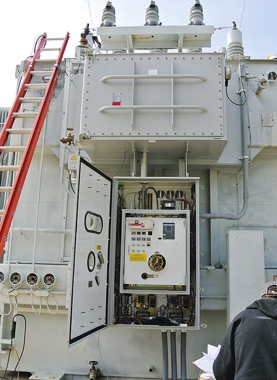
8. Motor drive unit
Motor dose units have to be maintained regularly. Maintenance interval and total expected lifetime depends on number of operations. Only trained and experienced personnel must carry out maintenance of motor drive units.
See transformer supplier’s documentation provided.
9. Oil filtering unit
The paper filter in the oil-filtering unit for the on-load tap-changer has to be changed when pressure loss has reached approximately 4 bars on the pressure gauge. You are advised to check the transformer supplier’s documentation.
10. Coolers
Coolers are cleaned by means of e.g. brushing inside the water tubes or air side vacuum cleaning when necessary. Need for cleaning is indicated by increased pressure loss, decreased temperature-difference oil/water/air in/out, increased transformer temperature, decreased water flow etc.
You are advised to check the transformer supplier’s documentation.
11. Liquid conservator with rubber diaphragm
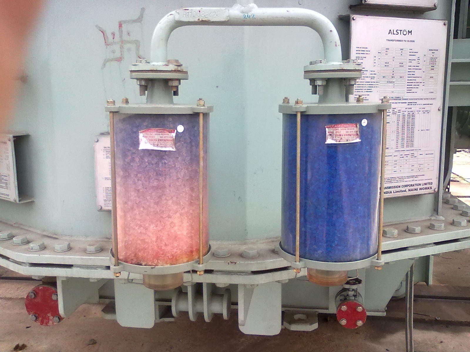
The system consisting of oil conservator with rubber sack does normally not require any other maintenance than inspection of the silica gel breather. The silica gel shall be changed when approx. 2/3 of the silica gel has changed from blue to red colour (old type of silica gel) or from pink to white, respectively.
12. Gaskets
The gaskets of the cover and flanges, as well as between bushings and cover, are usually made of liquid resistant vulcanised cork sheet, nitrite rubber or silicone sealant.
When tightening the gaskets special care must be taken to prevent the breaking of screws (bolts) or the gasket “floats away” (if not in a groove) caused by the heavy pressure. In particular stud nuts must be tightened very carefully.
13. Dry-type transformers
Dust and dirt on the transformer leads to reduced dialectical strength and cooling due to different environmental conditions where ventilated dry type transformers are installed. A periodic program for cleaning should be established for each installation.
In addition to cleaning the following should also be carried out during the inspection:
- The condition of external bolted electrical connections shall be checked and retightened.
- Loose winding clamps shall be retightened.
- The function of all warning devices shall be checked.
- Cooling fans shall be cleaned like the transformer. Afterwards, check their function and operation.
14. Surface protection
14.1. Painted surfaces
When repairing damaged paint, the points to be repainted should be cleaned from rust, dirt and grease before priming with a zinc rich primer prior to top coat paint. The final paint thickness should at least be equal to the original paint thickness.
By major paint damages contact with a specialised surface coating company is recommended.
14.2 Zinc coated surfaces
Zinc coated surfaces have a self-repairing, passivating, characteristic. Small damages as scratches do normally not need repairing. Larger areas, above 50 mm2, may need repair. After thoroughly cleaning apply zinc-rich (between 65-69% zinc by weight, or >92% by weight metallic zinc in dry film) paint to at least the same thickness as the original zinc coating.
Do not remove any original zinc during cleaning. The paint may be one-component (preferred) or two-component.
Sources:
- Transformer handbook by ABB


What is bleeding as regards to feeling oil into the transformer bushing or hollow pipes
What are causes of oil mixing of tap changer unit and main tank of power Transformer.
Good and effective maintenance prolongs the life of the equipment and ultimately contribute to reliable plant operation. Thank you, Edvard, for this useful article on transformer maintenance.
Exactly, Raymundo!
Very useful,thank you for sharing your knowledge, they come to reinforce electrical engineering criteria.
Amizing topic
Many many thanks for your support and informations that you publish, since long time we follow you on that site EEP
Thank you Ben, that’s very kind if you.
Very Nice
Even he don’t know the of yellow colour
Thank you for the valuable information. These type of information is really necessary as this is field/site knowledge which is generally not available in books in such a vivid fashion.
Very useful
Very nice and useful article
Topic presentation very elaborate. Keep it up