
Estimated Study Time: 9 minutes
Transformer operating limitations
There are few operating limitations that make transformer far from ideal. Generally, some of transformer operating limitations can be minimized, but not in total, never in total.
 6 transformer operating limitations that make it far from ideal (on photo: Transformer core; credit: texanstone.com)
Let’s talk about these limitations.
- Transformer losses (Heat)
- Copper (or winding) losses
- Iron (or core) losses
- Transformer temperature limitations
- Current limits
- Voltage and frequency limits
1. Transformer Losses (Heat)
The thermal ratings of a transformer are determined by the following three factors:
- The amount of heat produced inthe windings and connections
- The amount of heat produced in the iron core
- How effectively the heat can be removed from the transformer when the thermal rating of the transformer is reached.At this point, the heat being produced must equal the heat being removed or dissipated – thermal equilibrium.
The efficiency of power transformers is high, especially, for large transformers at full load. However, losses are present in all transformers. These losses may be classified as copper or I2R losses and core or iron losses.
Go back to Transformer operating limitations ↑
2. Copper (or Winding) Losses
Copper losses are resistive and proportional to load current and are sometimes called “load losses” or “I2R losses”. As the transformer is loaded, heat is produced in the primary and secondary windings and connections due to I2R. At low loads, the quantity of heat produced will be small but as load increases, the amount of heat produced becomes significant.
At full load, the windings will be operating at or near their design temperature.
Figure 1 shows the relationship between load-current and the heat produced in transformer windings and connections.

Go back to Transformer operating limitations ↑
3. Iron (or Core) Losses
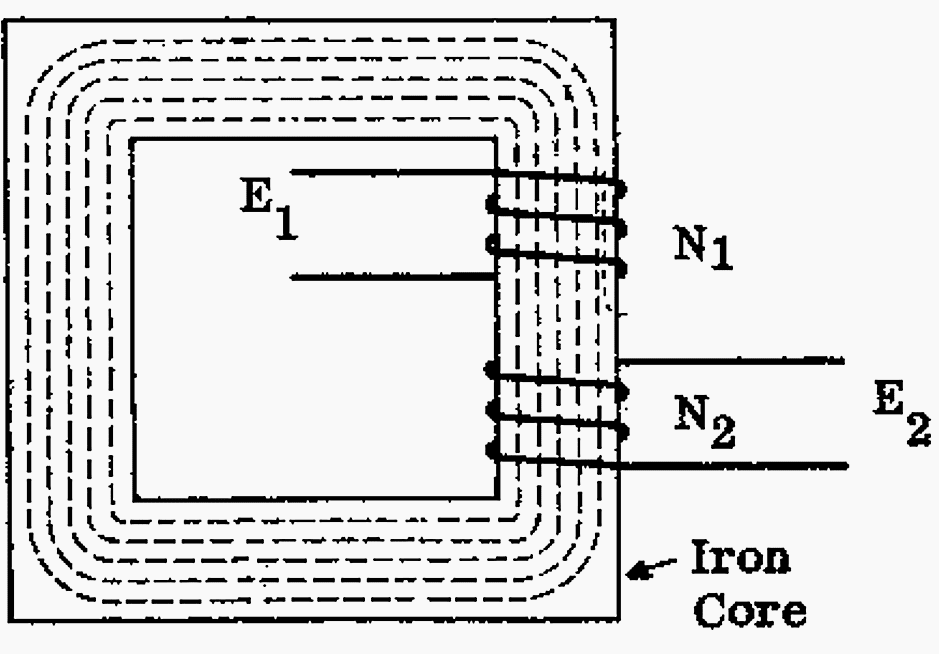
The iron loss is due to stray eddy currents formed in the transformer core. As you probably know, lines of flux are formed around the current-carrying conductors. The majority of the flux is as indicated in the following Figure 2, flowing around the core.
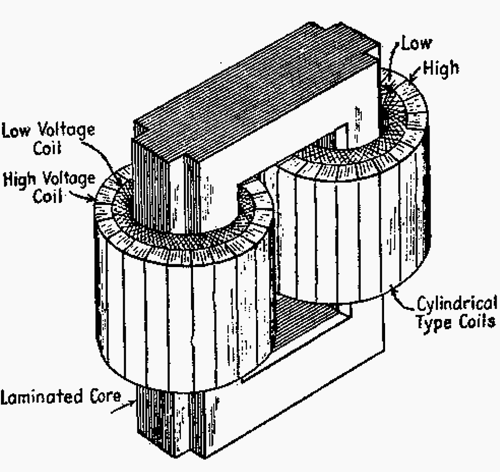
Some of the flux however, will try to flow at angles to the core and will cause eddy currents to be set up in the core itself. The term eddy is used because it is aside from the main flow. To combat this effect, the core is laminated as illustrated in Figure 2.
The laminations provide small gaps between the plates. As it is easier for magnetic flux to flow through iron than air or oil, stray flux that can cause core losses is minimized.
Some of the flux however, will try to flow at angles to the core and will cause eddy currents to be set up in the core itself. The term eddy is used because it is aside from the main flow. To combat this effect, the core is laminated as illustrated in Figure 3. The laminations provide small gaps between the plates.
As it is easier for magnetic flux to flow through iron than air or oil, stray flux that can cause core losses is minimized.
Go back to Transformer operating limitations ↑
4. Transformer Temperature Limitations
For dry (air-cooled) transformers (that normally have their windings insulated with silicone resin), a temperature limit of 155°C is usually imposed. Allowing air to circulate through the windings and over the core cools these transformers. Assuming a maximum ambient temperature of 40°C, then the temperature rise is limited to 155° – 40° = 115°C.
For oil-insulated transformers, there is usually a measurement of oil temperature and winding temperature provided. The simulated winding temperature is called hot-spot. It is derived by passing a representative amount of load current through a resistor located in the oil and measuring the resulting temperature (see Figure 4).
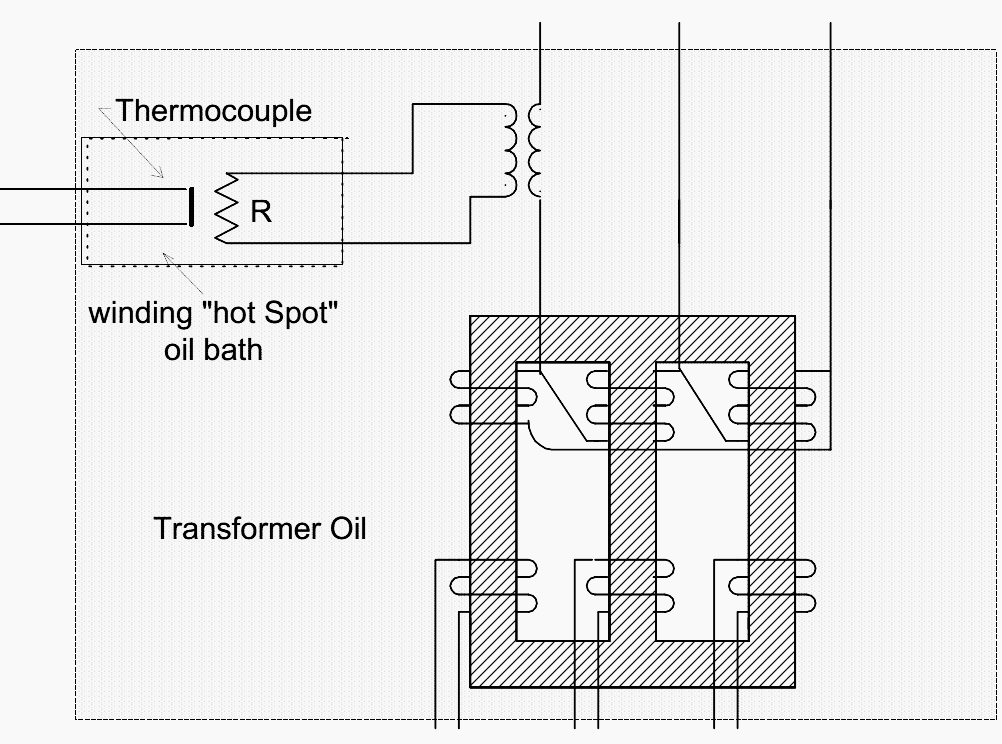
Note // The oil and hot spot temperatures are very important to be monitored. If sufficient cooling is not available the transformer load will have to be reduced.
Go back to Transformer operating limitations ↑
5. Current Limits
Current has two direct effects on the transformer:
- It produces heat in the windings of the transformer as we have just discussed above.
- It produces a voltage drop across the output winding proportional to the load current. As the transformer is loaded, the secondary voltage will fall due to the affects of winding resistance and reactance.
Go back to Transformer operating limitations ↑
6. Voltage and Frequency Limits
We have previously discussed how the operating voltage and frequency must be kept within rated values due to the physical design (winding insulation and core construction). The subtle effect of these parameters on the overheating of the core is sometimes overlooked.
When any transformer is operating at its rated voltage and frequency, it will be operating with its rated value of flux in the core.
If the voltage rises while the frequency remains constant, or the frequency falls while the voltage remains constant, the core flux will increase. The core will heat up due to the effects of hysterisis and eddy currents in the core.
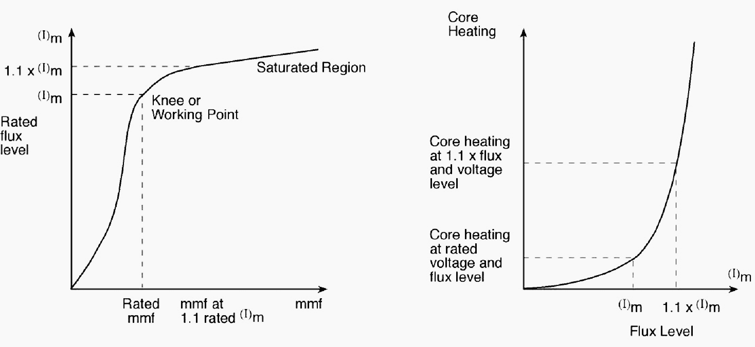
A voltage increase of 10% above the rated value will give a flux level of 10% above its rated value. From Figure 5, it can be seen that, if the flux level is 10% above normal, the iron has commenced to saturate.
Failure to observe this precaution will cause overheating of the core.
This overheating may cause the insulation which coats each of the laminations to fail, larger eddy currents will flow and extreme heating will follow. This can lead to a core failure, where in extreme cases. There will be melting of the iron laminations.
Go back to Transformer operating limitations ↑
Reference // Science and Reactor Fundamentals – Electrical CNSC Technical Training Group
Related electrical guides & articles


Edvard Csanyi
Hi, I'm an electrical engineer, programmer and founder of EEP - Electrical Engineering Portal. I worked twelve years at Schneider Electric in the position of technical support for low- and medium-voltage projects and the design of busbar trunking systems.I'm highly specialized in the design of LV/MV switchgear and low-voltage, high-power busbar trunking (<6300A) in substations, commercial buildings and industry facilities. I'm also a professional in AutoCAD programming.
Profile: Edvard Csanyi

Is there any formula to measure hot spot temperature of transformer winding??
Thank you