
Estimated Study Time: 9 minutes
Transformer Operational Concerns
Even with the best engineering practices, abnormal situations can arise that may produce damage to power transformer and other equipment and compromise the continuity of the delivery of quality power from the utility.
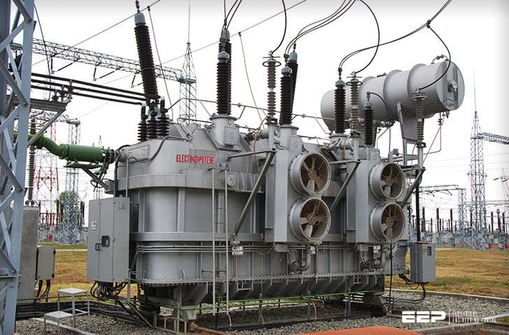 3 Common Transformer Phenomena That Should Worry Substation Engineers (on photo: power transformer 200 MVA 231/121/10.5 kV in Romania; credit: ELECTROPUTERE)
So, let’s say a word about three transformer phenomena that every substation engineer should be aware:
1. Ferroresonance
Ferroresonance is an overvoltage phenomenon that occurs when charging current for a long underground cable or other capacitive reactance saturates the core of a transformer.
Such a resonance can result in voltages as high as five times the rated system voltage, damaging lightning arresters and other equipment and possibly even the transformer itself.
A typical ferroresonance situation is shown in Figure 1 and consists of long underground cables feeding a transformer with a delta-connected primary.
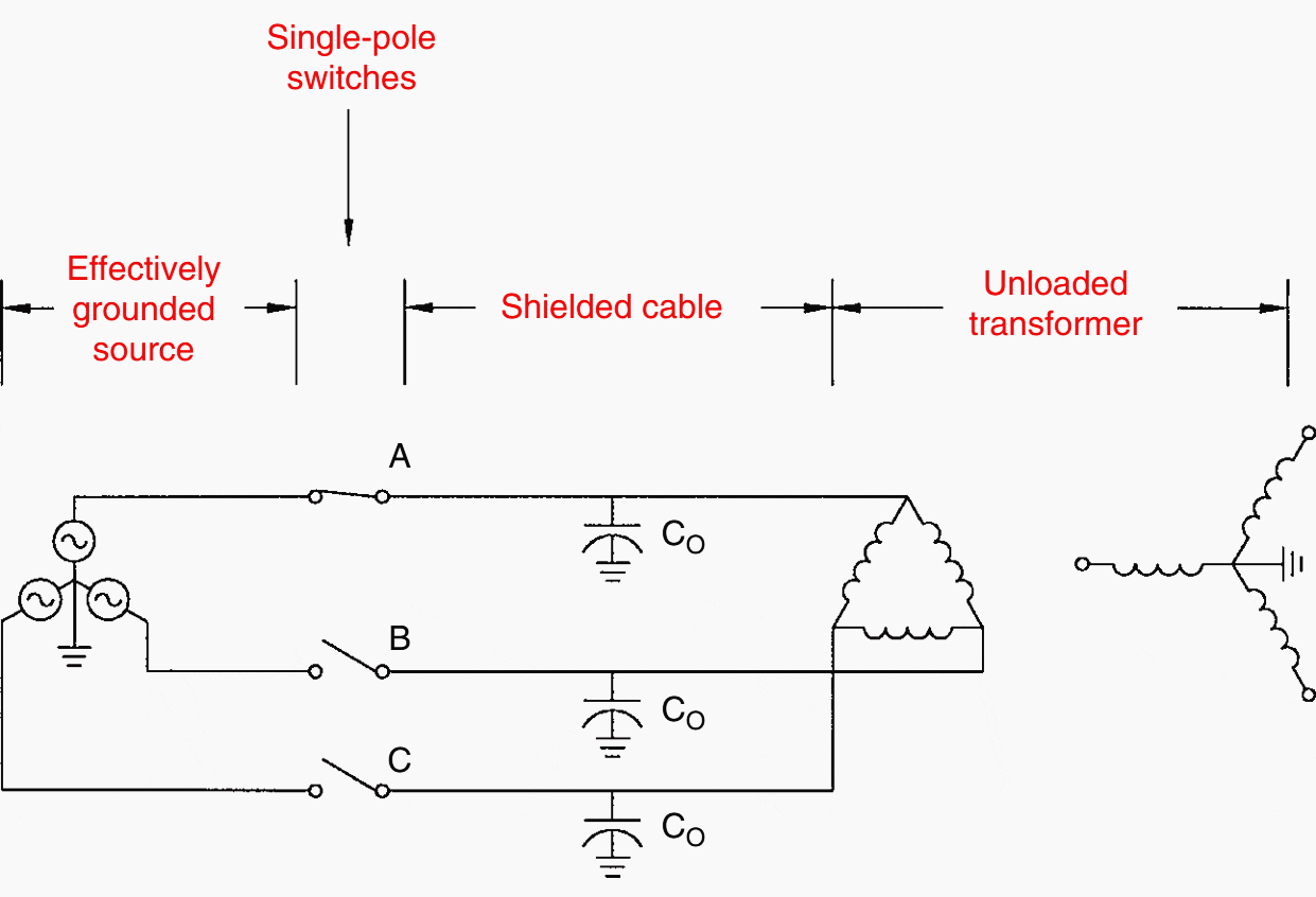
The transformer is unloaded or very lightly loaded and switching or fusing for the circuit operates one phase at a time.
Ferroresonance is more likely to occur on systems with higher primary voltage and has been observed even when there is no cable present. All of the contributing factors – delta or wye connection, cable length, voltage, load, single-phase switching – must be considered together.
Attempts to set precise limits for prevention of the phenomenon have been frustrating.
2. Tank Heating
Another phenomenon that can occur to three-phase transformers because of the common core structure between phases is tank heating.
Wye–wye-connected transformers that are built on four-legged or five-legged cores are likely to saturate the return legs when zero-sequence voltage exceeds about 33% of the normal line-to-neutral voltage.
Eddy currents produced by magnetic flux in the ferromagnetic tank steel will produce tremendous localized heating, occasionally burning the tank paint and boiling the oil inside.
For most utilities, the probability of this happening is so low that it is not economically feasible to take steps to prevent it, other than keeping trees trimmed. A few, with a higher level of concern, purchase only triplex transformers, having three separate core–coil assemblies in one tank.
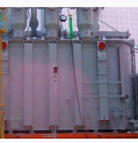
Evaluation of tank temperatures on power transformer
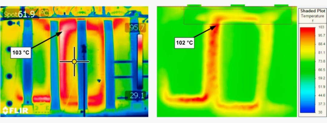
On a 280 MVA three phase transformer unit measurement of tank temperatures were made during heat run test. Phase current on the LV side was 5,2 kA. Transformer tank during heat run test is shown in Figure 2 below.
Both winding and LV leads as well as all material properties in calculations were modeled. Including leads in a transformer model makes the model very demanding as the number of elements increase and computational time increases drastically.
Tank was modeled without additional details what made calculation results not fully accurate but comparable to a real transformer.
Hotspots on tank were located correctly. Calculated hotspot value was 102 °C while measured 103 °C.
3. Polarity and Angular Displacement
The phase relationship of single-phase transformer voltages is described as ‘‘polarity.’’ The term for voltage phasing on three-phase transformers is ‘‘angular displacement.’’
3.1 Single-Phase Polarity
The polarity of a transformer can either be additive or subtractive. These terms describe the voltage that may appear on adjacent terminals if the remaining terminals are jumpered together.
Thus, the transformers built to ANSI standards today are additive if the voltage is 8,660 or below and the kVA is 200 or less. Otherwise they are subtractive. This differentiation is strictly a U.S. phenomenon.
Distribution transformers built to Canadian standards are all additive, and those built to Mexican standards are all subtractive. Although the technical definition of polarity involves the relative position of primary and secondary bushings, the position of primary bushings is always the same according to standards.
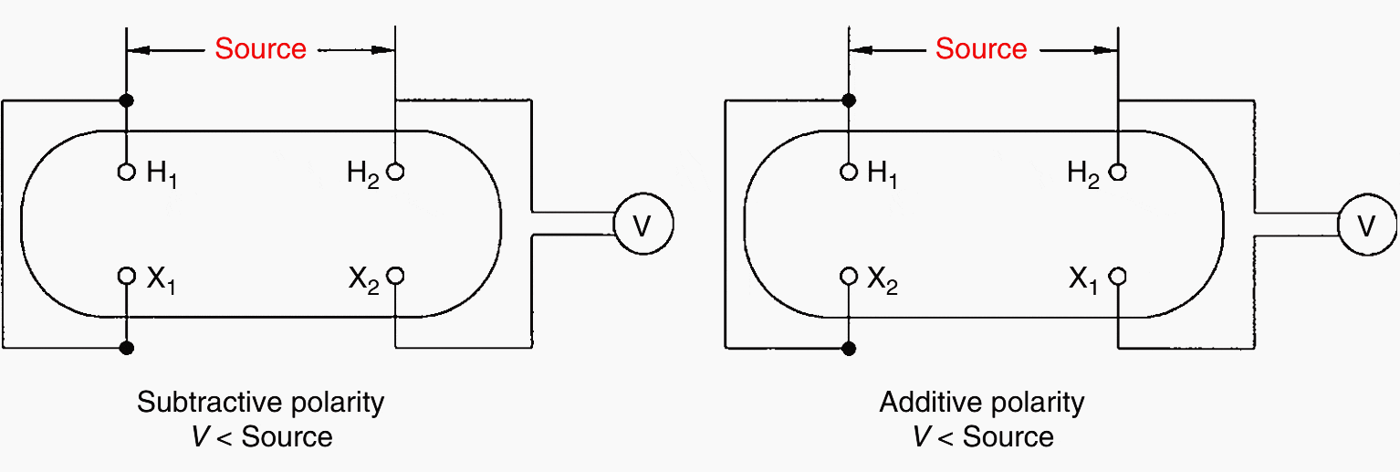
Therefore, when facing the secondary bushings of an additive transformer, the X1 bushing is located to the right (of X3), while for a subtractive transformer, X1 is farthest to the left. To complicate this definition, a single-phase pad-mounted transformer built to ANSI standard Type 2 will always have the X2 mid-tap bushing on the lowest right-hand side of the low-voltage slant pattern.
Polarity has nothing to do with the internal construction of the transformer windings but only with the routing of leads to the bushings.
Polarity only becomes important when transformers are being paralleled or banked. Single-phase polarity is illustrated in Figure 4.
3.2 Three-Phase Angular Displacement
The phase relation of voltage between H1 and X1 bushings on a three-phase distribution transformer is referred to as angular displacement. ANSI standards require that wye–wye and delta–delta transformers have 0° displacement.
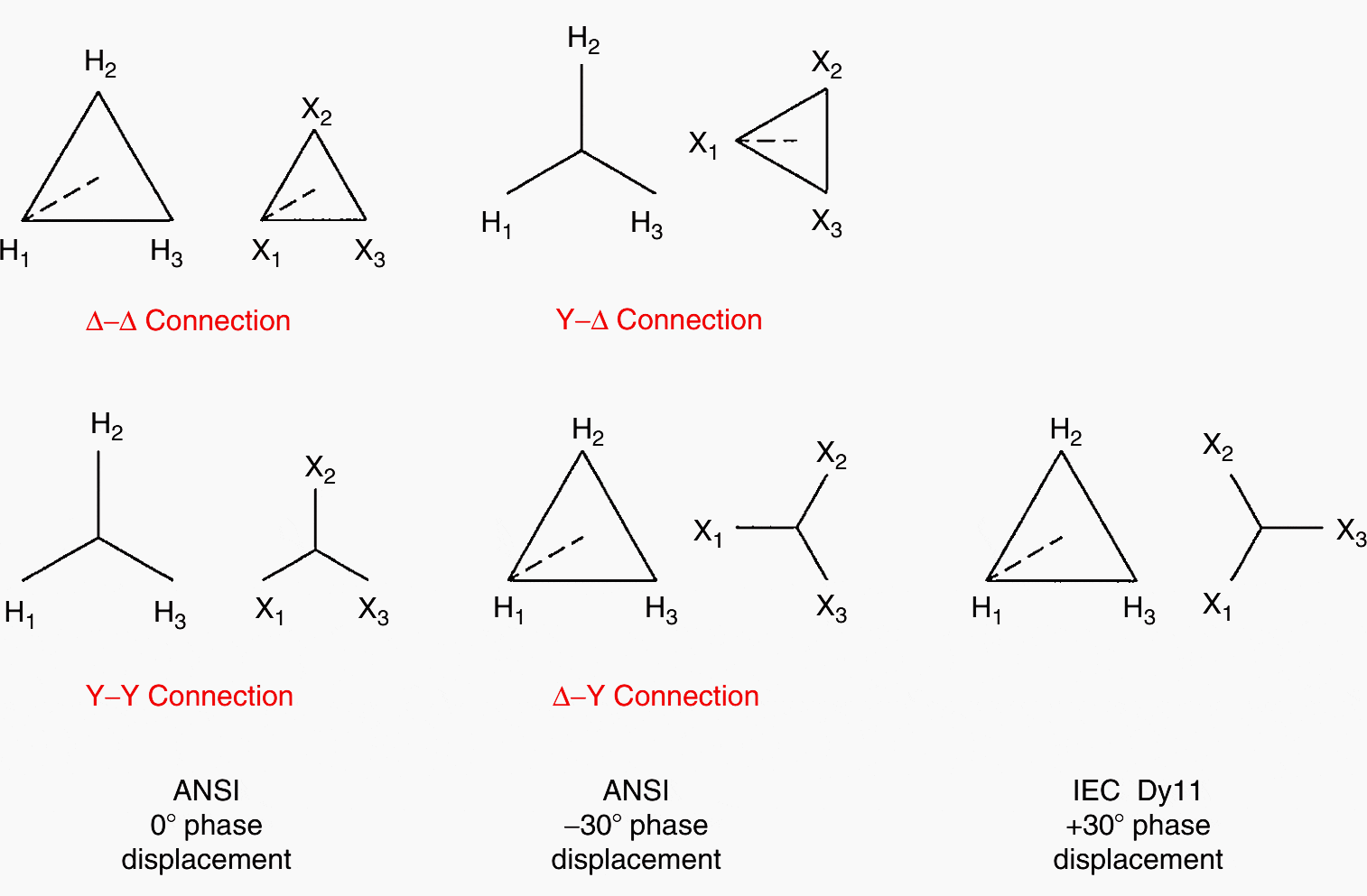
Wye–delta and delta–wye transformers will have X1 lagging H1 by 30°. This difference in angular displacement means that care must be taken when three-phase transformers are paralleled to serve large loads.
This IEC designation is interpreted as Delta primary–wye secondary, with X1 lagging H1 by 11 × 30° = 330°, or leading by 30°.
The angular displacement of Dy11 differs from the ANSI angular displacement by 60°. Three-phase angular displacement is illustrated in Figure 5 above.
References //
- Electric Power Engineering Handbook by Leonard L. Grigsby (Purchase hardcover from Amazon)
- Prediction of local temperature rise in power transformer tank by FEM by Robert Sitara, Ivan Šulca and Žarko Janić (4th International Colloquium “Transformer Research and Asset Management”)
Related electrical guides & articles


Edvard Csanyi
Hi, I'm an electrical engineer, programmer and founder of EEP - Electrical Engineering Portal. I worked twelve years at Schneider Electric in the position of technical support for low- and medium-voltage projects and the design of busbar trunking systems.I'm highly specialized in the design of LV/MV switchgear and low-voltage, high-power busbar trunking (<6300A) in substations, commercial buildings and industry facilities. I'm also a professional in AutoCAD programming.
Profile: Edvard Csanyi

Hola, Edvard / EPP
Muchas gracias por la Informacion.:
Electric Power Transformer Engineering, Third Edition
Edited by James H. Harlow
Saludos
Luis Sanchez M.
Thank you EEP!
With manufacturers pushing advanced software and techniques for monitoring and diagnostics it’s good to get back to basic engineering and fundamentals To analyze problematic circumstances!
Thank you for your very informative article.
One little comment. When yo have Delta-Wye transformers and that you install transformer differential protection, it is important to know if you use the +30 or -30 XFO, otherwise it will create a mismatch in the differential element, which will create false trip when the load current gets to the trig point. Regards, Guy R.
Thanks for EEP first of all.
A kindly note for Figure 4, it should be V > Source for Additive Polarity.
Lot of Thanks for sharing your knowledge to us.
Thank you very much for sharing your knowledge.
EEP is very resourceful for me.
Best regards,
Joseph