
Estimated Study Time: 29 minutes
Transformer Failure Incidents
This technical article deals with transformer failure incidents due to nuisance tripping caused by various design flaws, operational conditions, or improper protection relay settings. The focus is on differential protection and ground protection, as they account for a considerable number of false tripping.
 The mystery of nuisance tripping incidents in transformer protection that worry engineers
I will try to explain two different case studies of primary substation 132/66 kV ∆/∆ and investigate the incident of feeders breakers tripped open although most of the loads were disconnected, and what went wrong and caused the transformers to go out of service.
1. Introduction to Power Transformers
Transformers are electrical devices that transfer power between two circuits at different voltage and current values using the principle of induction discovered by Faraday in 1831. Devices that are based on the Faraday law like inductors used to be in laboratories till the AC was launched near the end of the 19th century.
The development of the AC power system and transformers almost occurred at the same time because they belong to they are interrelated.
Transformers vary in types, rating, and design to suit the different connected load types, but they follow the same principle of operations and they do have the same construction (more or less).
In the following, a list that contains most transformer components could be identified:
- Magnetic circuit: It consists of a core and yoke that provides a path for magnetic flux.
- Electric circuit: It is the primary and secondary winding that form the transformation voltage ratio. Transformers are categorized as shell type or core type according to the primary/secondary winding arrangement.
- Dielectric circuit: It is composed of insulation used in different places within transformers.
- Tank and accessories: Accessories differ from transformer to transformer based on the specifications and applications. They include conservator, breather, explosion vent, radiator, bushings, and many others.
Transformers are prone to nuisance tripping as a result of design flaws, operational conditions, improper relay settings, or otherwise. Transformers are a major component of substations and many times it is not affordable to have accidental outages, especially for bulk substations that serve large areas.
The main principles are explained briefly and two case studies are discussed to highlight what went wrong and caused the transformers to go out of service.
2. Transformer Types
Many classifications exist for transformers that are based on different criteria. The transformers are classified according to functionality (step-up/down), insulation (oil or air), indoor/outdoor, and some other categories. That being said, it is common in the industry to have two transformer types: distribution transformers and power transformers (see Figures 2a and 2b).
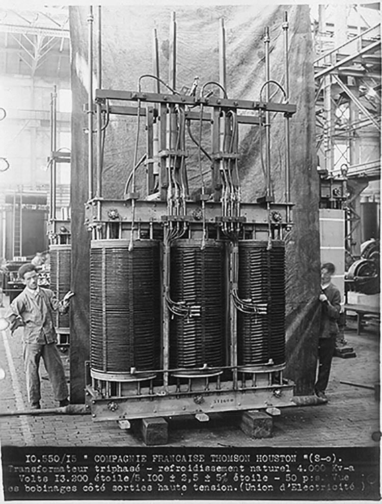
Figure 2a – Power transformer
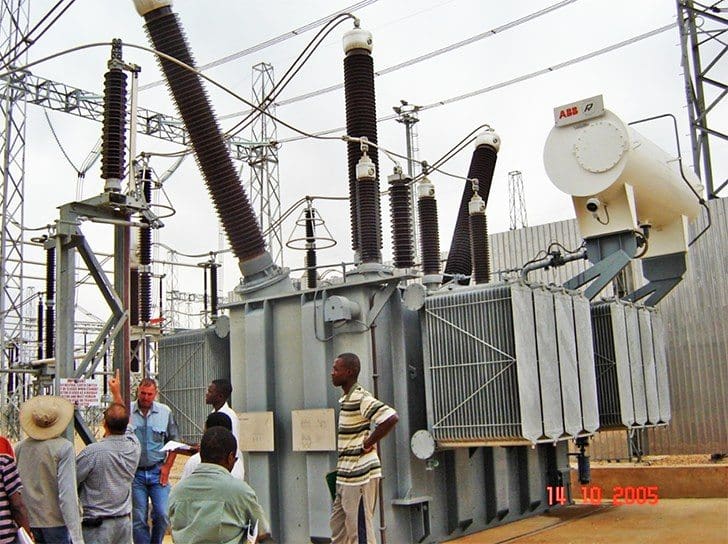
Figure 2b – Distribution transformer

The main features of each type are listed in Table 1 below.
Oil is a surrounding medium that acts as an insulating and heat transfer medium to protect the core and coil structure. A liquid preservation system is used to protect the contained oil and to prevent its contamination from the surrounding atmosphere. The purity of the insulating medium (oil) becomes increasingly important at higher voltages due to the electrical stress exerted on the oil.
Different liquid preservation systems exist that apply for different ratings and applications. The following are common liquid preservation systems used in industry:
- Sealed tank
- Positive-pressure inert gas
- Gas-oil seal
- Conservator tank
Table 1 – Transformer Types in Power Grids
| Basis | Power Transformer | Distribution Transformer |
| Size | Larger in size with complex installation | Smaller in size and flexible installation |
| Operation | Step-up/down (generation & transmission) | Step down (distribution) |
| Load | Always operates at full low 90-100 % | Varying load |
| Rating | 33 kV, 66 kV, 110 kV, 200 kV, & 400 kV (generally over 200 MVA) | 230 V, 400 V, 3.3 kV, 6.6 kV, & 11 kV (generally less than 200 MVA) |
| Efficiency | 100 % at full load | 100 % at 50-70 % load |
2.1. Applications that Impact Transformer Protection
A flashover in an off-load tap changer is of a failure type that could be repaired in the field, but if it develops into a winding failure, it surely needs a repair in a specialized facility. Consequently, a special protection function that senses the tap changer fault is important.
Moreover, substantial external faults fed by transformers exert so much mechanical stress and thermal stress against the transformer winding that along through fault can put the transformer internal components at great risk. This mandates a fast clearing for a close-in external fault is desirable. Transformers that are readily replaceable do no need advanced protection schemes.
Occasionally, transformers protection functions cover external buses and cables, and faults in these zones expose personnel to arc flash hazards, so slow clearing protection is not acceptable.
Recommended Reading – How do faults develop in HV transformer?
How do faults develop in a HV transformer and why condition monitoring is important
Fires in indoor transformers could put the facility’s safety as well as personnel safety at risk. Also, transformers in hazardous areas and transformers used in generation plants are all vital and require fast clearing protection to avoid any ramifications after faults. Some transformers are custom designs and their lead time is so long that its replacement is not an option, which again mandates fast clearing protection.
Generally, a proportional relationship exists between the transformer lead time and the protection function scheme. The longer the lead time is, the more advanced the protection scheme is.
Related electrical guides & articles


Salem Alshahrani
Electrical engineer (BEE & Meng). Specialized in substation design, especially in LV/MV switchgears and transformers. Passionate in power system planning, analysis, and stability studies.Profile: Salem Alshahrani
