Best transformer protection vs cost
This technical article relies on the previously published article (6 alarms coming from a substation transformer you MUST take very seriously), but is much more dedicated to the implementation of relay protection principles. You know that transformer is one of the most important links in a transmission system. Unfortunately, its great range of characteristics and special features makes complete protection difficult.

The choice of suitable protection for transformers also is governed by cost, as the ratings required in transmission, and distribution systems, range from a few kVA to several hundred MVA.
Fuses are used for the lower rated transformers. Higher ratings, however, require the best protection that can be designed.
The most common principles adopted in transformer protection include the following:
- Overheating protection
- Overcurrent protection
- Earth fault protection (restricted and standby)
- Biased differential protection
- Gas detection protection, and
- Overfluxing protection (large transformers or where a risk of over flux exists).
1. Overheating Protection
The rating of a transformer is based on the temperature rise above an assumed maximum air temperature. An oil temperature of about 95°C is considered to be the maximum working value beyond which a further rise of 8-10°C will have a detrimental effect on the transformers insulation. It will lower the life of a transformer, if sustained.
Large transformers have oil and/or winding temperature detection devices. Both direct (oil) and indirect (winding) methods of temperature measurement may be employed, or a combination of both.
Generally, these devices are fitted as shown in Figure 1.


LEGEND:
- A – Temperature sensitive bulb
- B – Capillary tube
- C – Bourdon tube
- D – Connecting rod
- E – Main spindle
- F – Plate carrying mercury switches
- G – Mercury switch in alarm circuit
- H – Mercury switch in circuit of motor associated with coolant circulation
- K – Mercury switch in contactor circuit of power lines
- L – Adjustment for operation point of mercury switch G
- M – Adjustment for operation point of mercury switch H
- N – Adjustment for operation point of mercury switch K
- O – Maximum pointer
- P – Scale
- Q – Audible warning device
- R – Signal lamp
- S – Electric motor associated with coolant circulation (air/oil)
- T – Indicating pointer
- U – Ambient temperature compenstator
The direct method for an instrument measuring oil temperature is shown in Figure 1 above. The temperature detecting element comprises a mercury filled steel bulb A. This is connected by a capillary tube B to a Bourdon tube C, which is fixed at one end.
Increases in temperature cause expansion in the mercury, resulting in increased pressure in the Bourdon tube. This causes the free end to deflect. The deflection causes the plate F to rotate.
Compensation for changes in air temperature is provided by the shaped bimetallic strip U fitted in the linkage between the Bourdon tube and the metal plate. Pointers T and O indicate the actual temperature of the bulb, as well as the maximum temperature to which it has been subjected.
The switches carry out the trip and/or alarm functions.
The same principle may be applied for the indirect method which measures the temperature of a transformer winding. A different type of detecting element is used from the plain bulb shown.
The mercury bulb is surrounded by a heater coil or a heater is included in the instrument. This is fed from a current transformer which reflects the actual current in the transformer winding. If the heater is suitably designed, the instrument can be arranged to measure either the winding average or ‘hot spot’ temperature. The hot spot temperature is more commonly used. (Note that the hot spot is the hottest spot in the windings caused by local heating.)
Generally, two winding temperature instruments are fitted to the larger power transformer. Each instrument is fitted with up to four switch contacts.
Table 1 shows typical settings for these instruments.
Table 1 – Typical temperature settings
| Winding Temperature | Oil Temperature | ||
| Instrument 1 | Instrument 2 | ||
| Coolers | In 90°C Out 73°C | Alarm | 95°C |
| Alarm | 120°C | ||
| Trip | 130°C | — | — |
Note In cases where forced cooling is not used, usually only an oil temperature instrument is fitted.
2. Overcurrent Protection
Protection against excess current was the earliest evolved protection system. From this basic principle, the graded overcurrent system was introduced for fault protection. Most system disturbances utilizing this method are detected with IDMT relays, that is, relays having:
- Inverse characteristic (the larger the fault current, the quicker is the operation), and
- Definite minimum time of operation.
The degree of overcurrent protection provided to a transformer by an IDMT relay is limited. Usually, settings of these relays must be high, that is, 150% to 200%. This is because the relays must not operate for emergency overload conditions.
Therefore, these relays provide negligible protection for faults inside the transformer tank.
3. Earth Fault (Restricted)
Generally, the simple overcurrent and earth fault scheme used in a typical line protection application does not give adequate protection to a star connected winding.
The protection system is operative for faults within the zone of the current transformers. Virtually complete cover for earth faults is obtained, particularly when the star point is solidly earthed.


Star and delta windings can be protected separately with restricted earth fault protection. This provides high speed protection against earth faults for the whole of the transformer with relatively simple equipment.
A typical earth fault protection for delta connected windings is shown in Figure 3. This diagram shows that the restricted earth fault scheme also protects the earthing transformer (an earth reference used to limit earth fault current).
The earthing transformer is protected by the main transformers differential and tank overpressure device (Buchholz).


4. Differential Protection
Differential protection is designed to cover the complete transformer. This is possible because of the high efficiency of transformer operation and the nearly equal ampere turns developed in the primary and secondary windings. (MVA ‘in’ approximately equals MVA ‘out’).
The principal causes of the spill current include the following:
Transformer Ratio
The rated currents on the primary and secondary sides differ in inverse ratio to the voltages. This difference is overcome mainly by the appropriate selection of current transformer ratios.
Tap Changing Facility
If the transformer has a tapping range, the voltage variation must be allowed for in the differential scheme. This is because the current transformers and connections are selected to balance at the nominal tap ratio of the transformer. Any variation in ratio away from the nominal tap position will produce an imbalance proportional to the voltage ratio changes.
Under certain conditions (particularly out of zone fault conditions), this imbalance current may be sufficient to operate the relay when operation is
not required.
To offset these spill effects, the protection relay selected usually includes a proportional amount of bias.
Magnetising Current Inrush
When a transformer is energized initially, magnetising current is required. The current appears only on the primary side of the transformer, therefore, the whole of the magnetizing current appears as an imbalance to the differential protection.
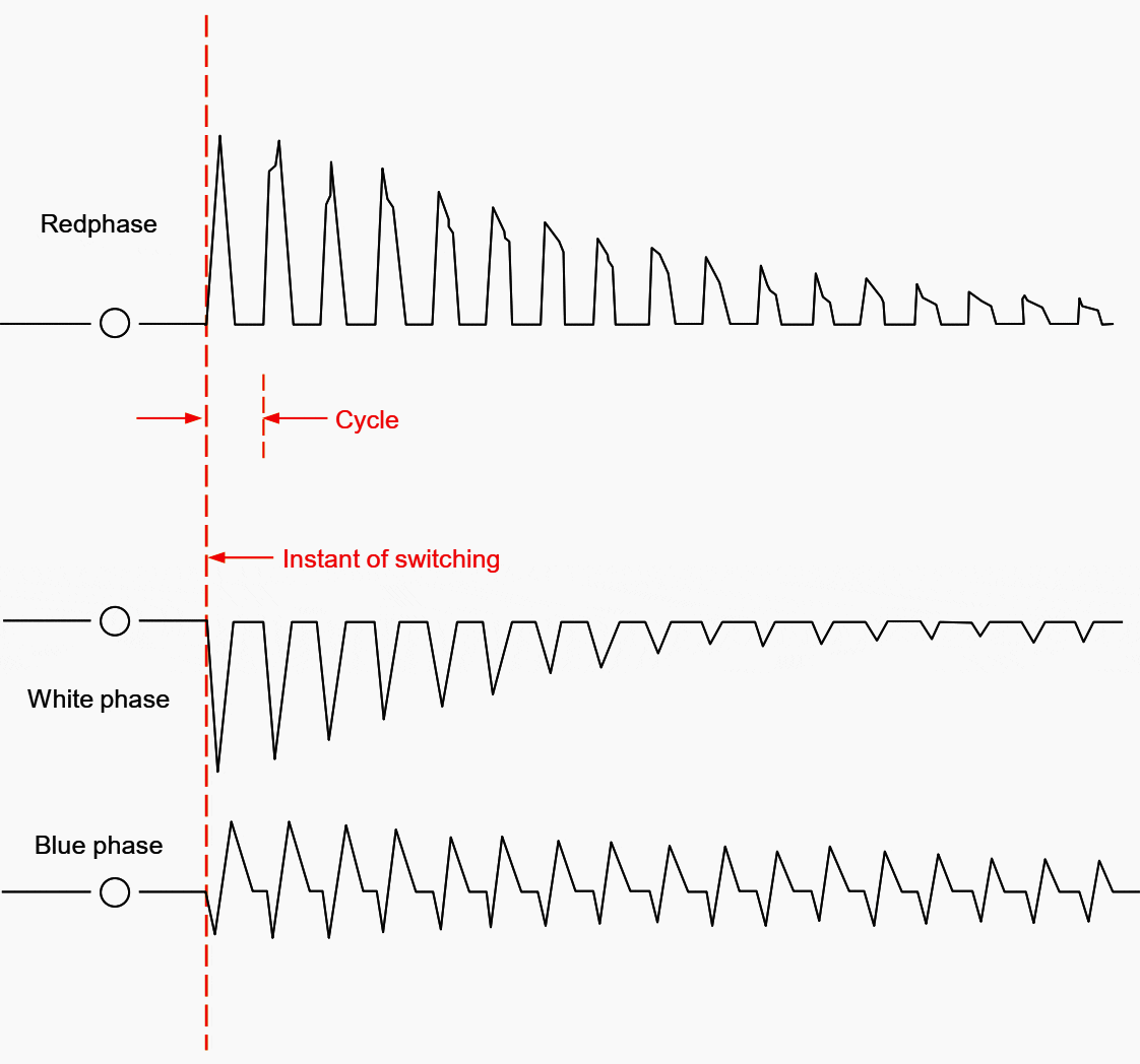
A typical oscillogram of transformer inrush currents, due to magnetizing the transformer core, is shown in Figure 4.


The initial peak value of the inrush current in any phase depends upon the instant of switching and the residual magnetic condition of the core. The maximum peak values equal up to 8 times the rated current of the transformer.
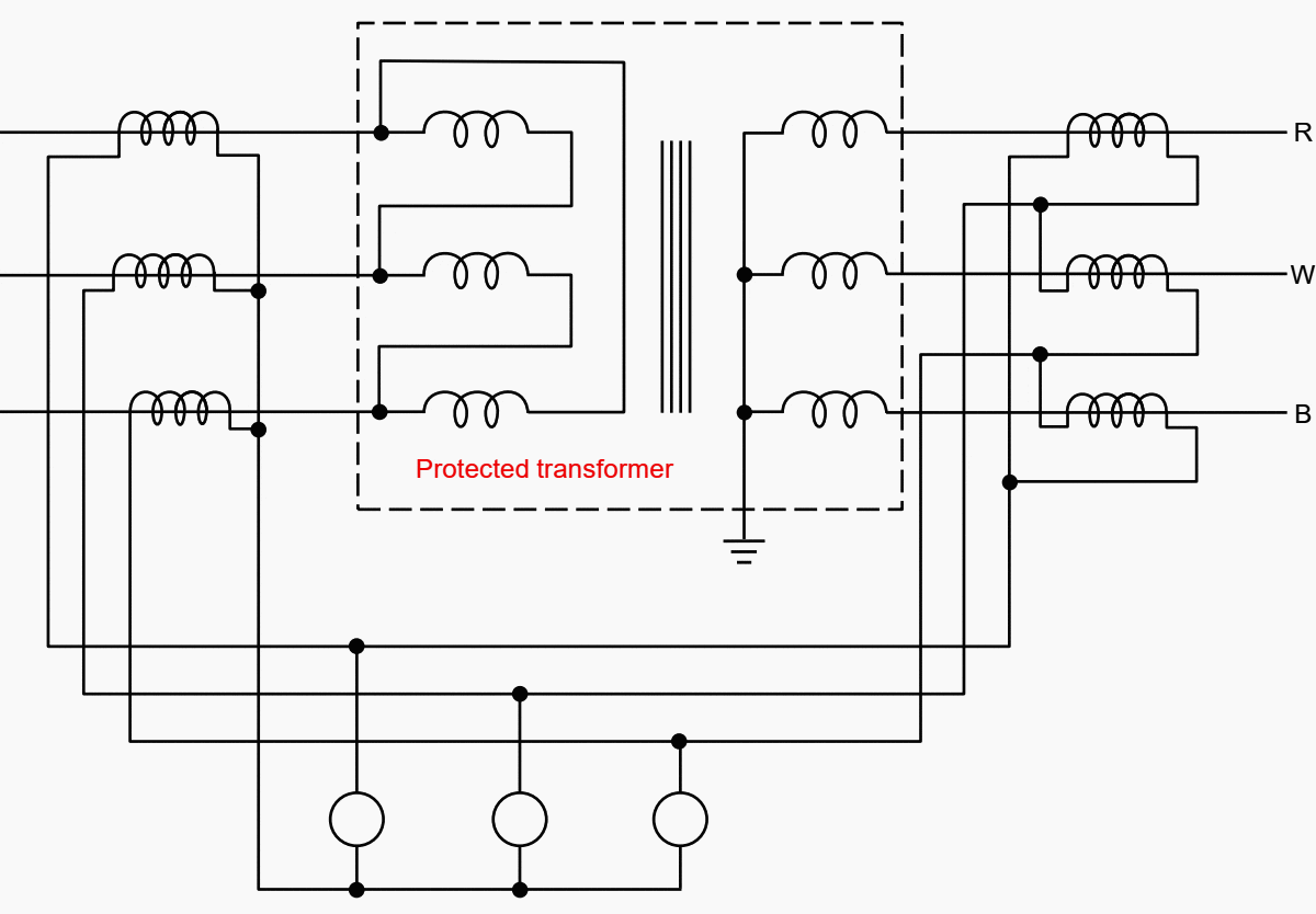
The basic unbiased scheme applied to a delta/star transformer is shown in Figure 5 below.
Balance is obtained by using star connected current transformers on the delta side of the transformer and delta connected current transformers on the star side with the correct ratio.


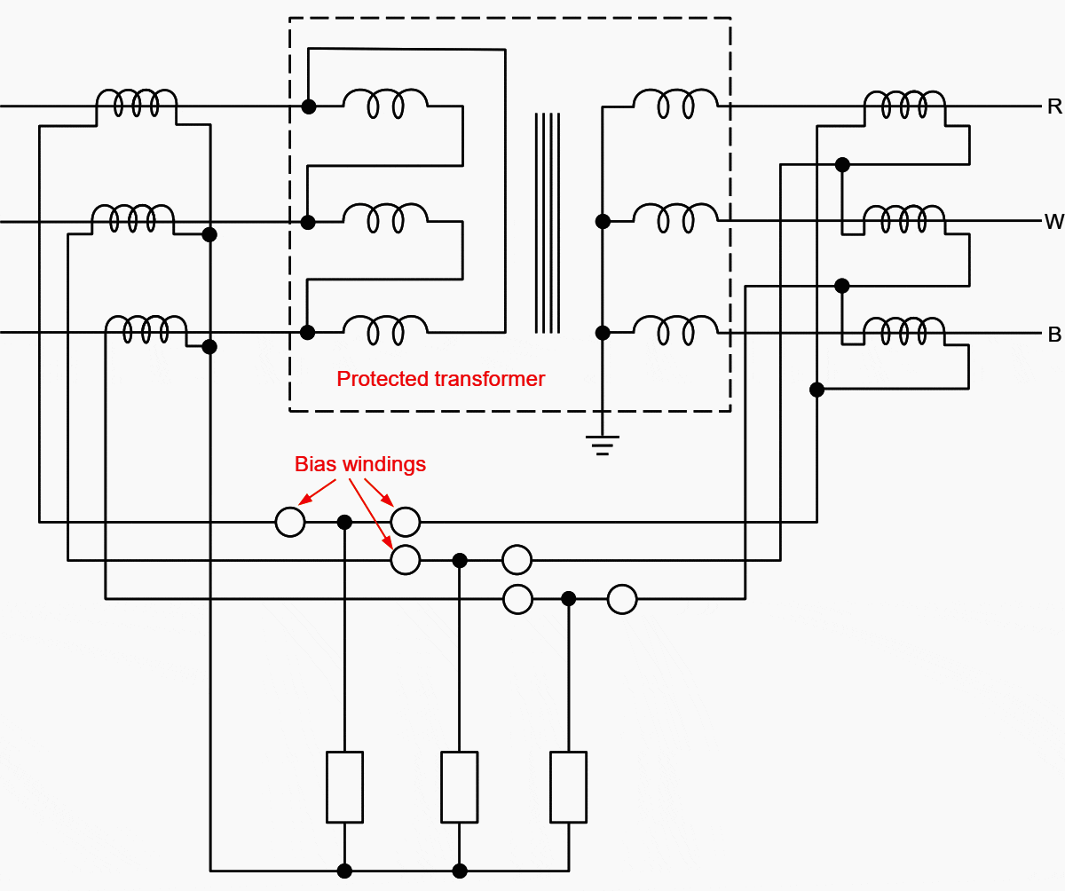
The protection of power transformers with variable ratio (due to on load tap changing equipment) must include a bias feature, if low fault setting and high operating speed are to be obtained.
The basic biased scheme applied to a delta/star transformer is shown in Figure 6.


5. Gas Detection
Faults inside oil immersed electrical plant (for example, transformers) cause gas to be generated. If the fault is severe, oil movement occurs.
The generation of gas is used as a means of fault detection in the gas/oil operated relay. This comprises one or two hinged vanes, buckets, or similar buoyant masses inserted into the pipework between the oil conservator and the transformer tank.
Figure 7 shows its general application.
A heavy fault will produce a rapid generation of gas. This causes violent displacement of the oil which moves the surge float system of the relay. It results in the closing of another pair of contacts (surge contacts) which are used to trip the transformer circuit breakers.


The gas/oil operated Buchholz relay is shown over in Figure 8. This relay gives the best possible protection against conditions such as incipient (low level) winding faults, core faults and short circuit situations.
The alarm element will operate for loss of oil, as will the trip element if the oil loss continues. This alarm and trip will sometimes operate under cold conditions if conservator oil levels are not maintained.
Analysis of a gas sample collected in a Buchholz chamber frequently may assist diagnosis of the type of fault. The rate of gas generation indicates the severity of the fault.
Tap changer selector switches, mounted separately from the main oil tank, can be provided with a separate oil/gas actuated relay. Alternately, the pipework may be arranged in such a manner that one relay is used for both tanks.
Transformers are fitted with pressure relief devices to prevent tank rupture in the event of a major internal fault. The old type consisted of a thin diaphragm at the top of a relief vent. The new type is a spring loaded self-resetting diaphragm which also activates a micro switch to trip the transformer.


6. Overfluxing
Transformer overfluxing is caused by overvoltage and/or a reduction in system frequency. Overvoltage causes an increase in the flux generated and stress on insulation. The increased flux density causes an increase in iron loss and an increase in magnetising current.
Flux is diverted from the laminated core of the transformer into the steel structure. This gives rise, particularly, to the core bolts carrying more flux
than their designed limits. Under these conditions, the core bolts may be rapidly heated to a temperature which destroys the insulation surrounding them.
This could damage the core insulation.
Reduction in frequency has the same effect of increasing core flux, therefore, it follows that a transformer can operate with some overvoltage, provided it is accompanied by an increase in frequency. However, the operation must not continue for prolonged periods with high voltage and low frequency conditions.
Overfluxing protection is used mostly on generator/transformer units. Overfluxing may occur when generators are run up for synchronisation to the system.
Source: Switching Operator’s Manual – Transmission Switching by Horizon Power


Dear sir,
We have 10MVA power transformer STAR-STAR in our 110/33KV Sub-Station and we have two Incomers the Transformer is tripping on Diffrential relay on all three pahses (RET 615) ABB make whenever one of the Incoming Supply fails .all the CTs connections are ok. can you explain me what is causing this type of tripping.your comments would be higly appreciated
You are great, Edvard, for sharing your even greater knowledge to many engineers and technical oriented individual. This is a big help to maintenance engineer like me. God bless you, Edvard.
Am a young engineer. I want to know if mercury oil and transformer oil the same.
What type of electrical transformers use mercury?
Where are Mercury located in electrical transformers?
I loved your article , can you please describe the way we do relay settings for
1) transmission line protection using ( distance (21) , Pott, dcb )
2) Transformer protection ( using differential ( 87 ) , 50/51 , 50/51G )
3) Busbar protection ( 87 )
4) Feeder protection ( 50/51, 50/51G)
you can take any arbitary example any arboitary line parameters , and calculated fault values and do the relay settings , it would be real helpful to my project and my new job to learn something for a knowledgable guy like you , again doesnt matter what the relay , I just want to know the basics , thank you
This is good staff.keep us posted. I want to be a member
Am excited to read your article which are more powerful.
Let be in touch for your advice .
Nice article. Very informative.
In Figure 1, mercury is already a banned substance. Any new materials replacing Mercury and its details? Thank you.
I got this information incidentally and since then getting very good articles on electrical engineering. what more benefits I will get by becoming membership.