
Estimated Study Time: 7 minutes
Protection schemes and relays selection
This technical article shows application hints for typical transformer protection schemes where SIPROTEC 4 relays are used. Some of applications are small and large transformer infeed, dual infeed with single transformer, parallel incoming transformer feeders, and others like parallel incoming transformer feeders with bus tie.
 Eight typical transformer protection schemes with correctly selected relays
Let’s see the most typical transformer applications and their protection schemes:
- Small transformer infeed
- Large or important transformer infeed
- Dual infeed with single transformer
- Parallel incoming transformer feeders
- Parallel incoming transformer feeders with bus tie
- Three-winding transformer
- Autotransformer
- Large autotransformer bank
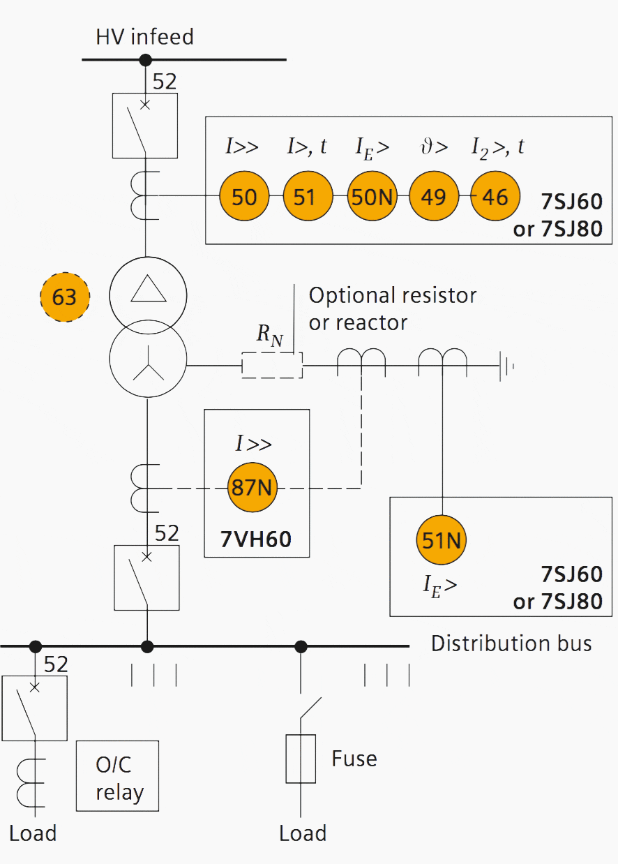
1. Small transformer infeed
Earth faults on the secondary side are detected by current relay 51N. However, it has to be time-graded against downstream feeder protection relays.
Primary circuit-breaker and relay may be replaced by fuses.
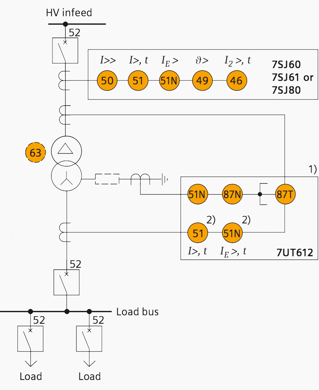
2. Large or important transformer infeed
Relay 7UT612 provides numerical ratio and vector group adaptation. Matching transformers as used with traditional relays are therefore no longer applicable.
Notes //
- If an independent high-impedance-type earth-fault function is required, the 7VH60 earth-fault relay can be used instead of the 87N inside the 7UT612. However, class × CT cores would also be necessary in this case (see small transformer protection).
- 51 and 51N may be provided in a separate 7SJ60 if required.
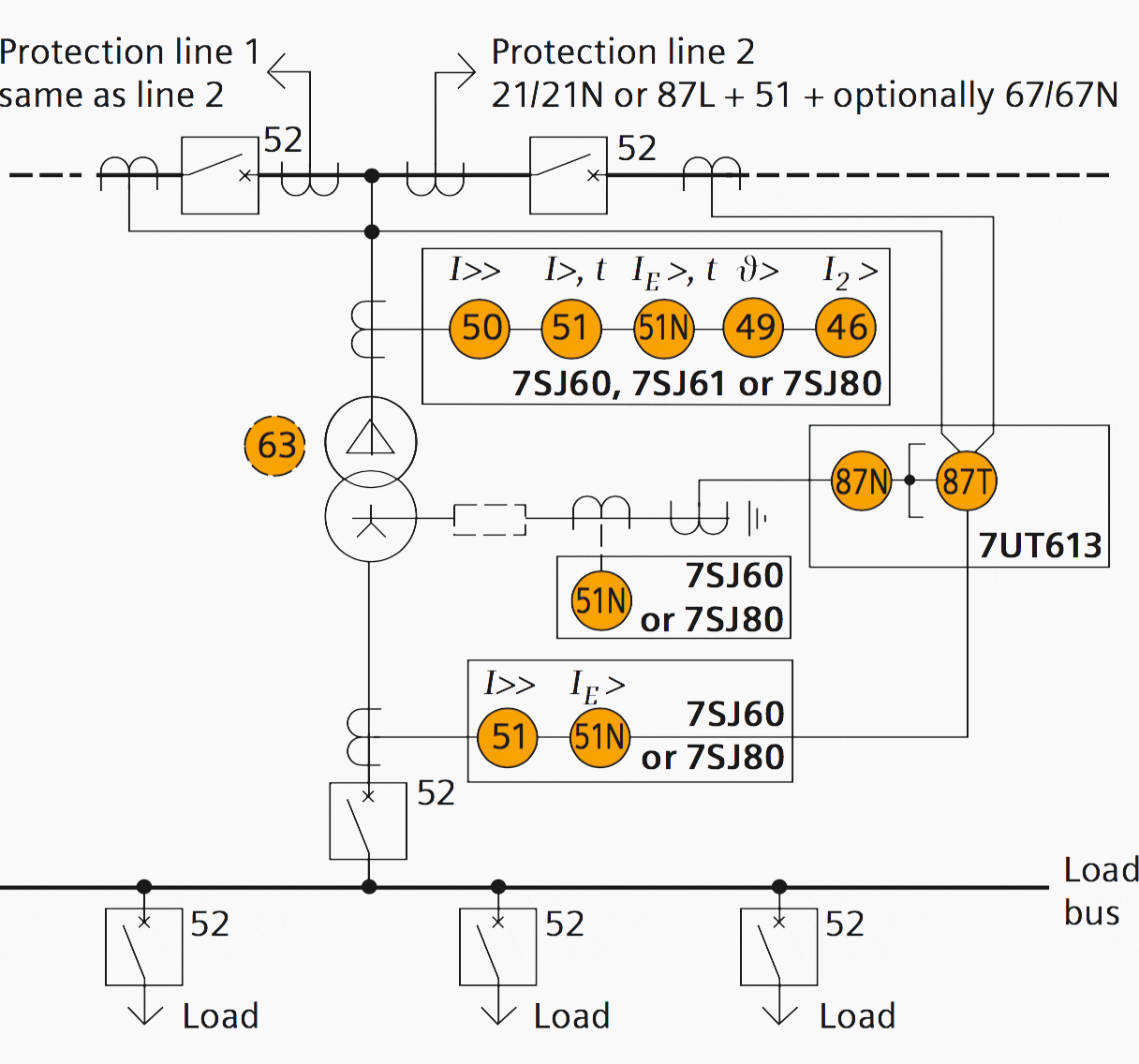
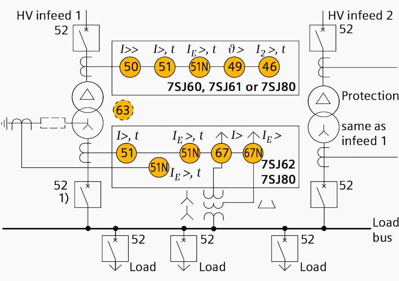
3. Dual infeed with single transformer
Line CTs are to be connected to separate stabilizing inputs of the differential relay 87T in order to ensure stability in the event of line through-fault currents. Relay 7UT613 provides numerical ratio and vector group adaptation.
Matching transformers, as used with traditional relays, are therefore no longer applicable!
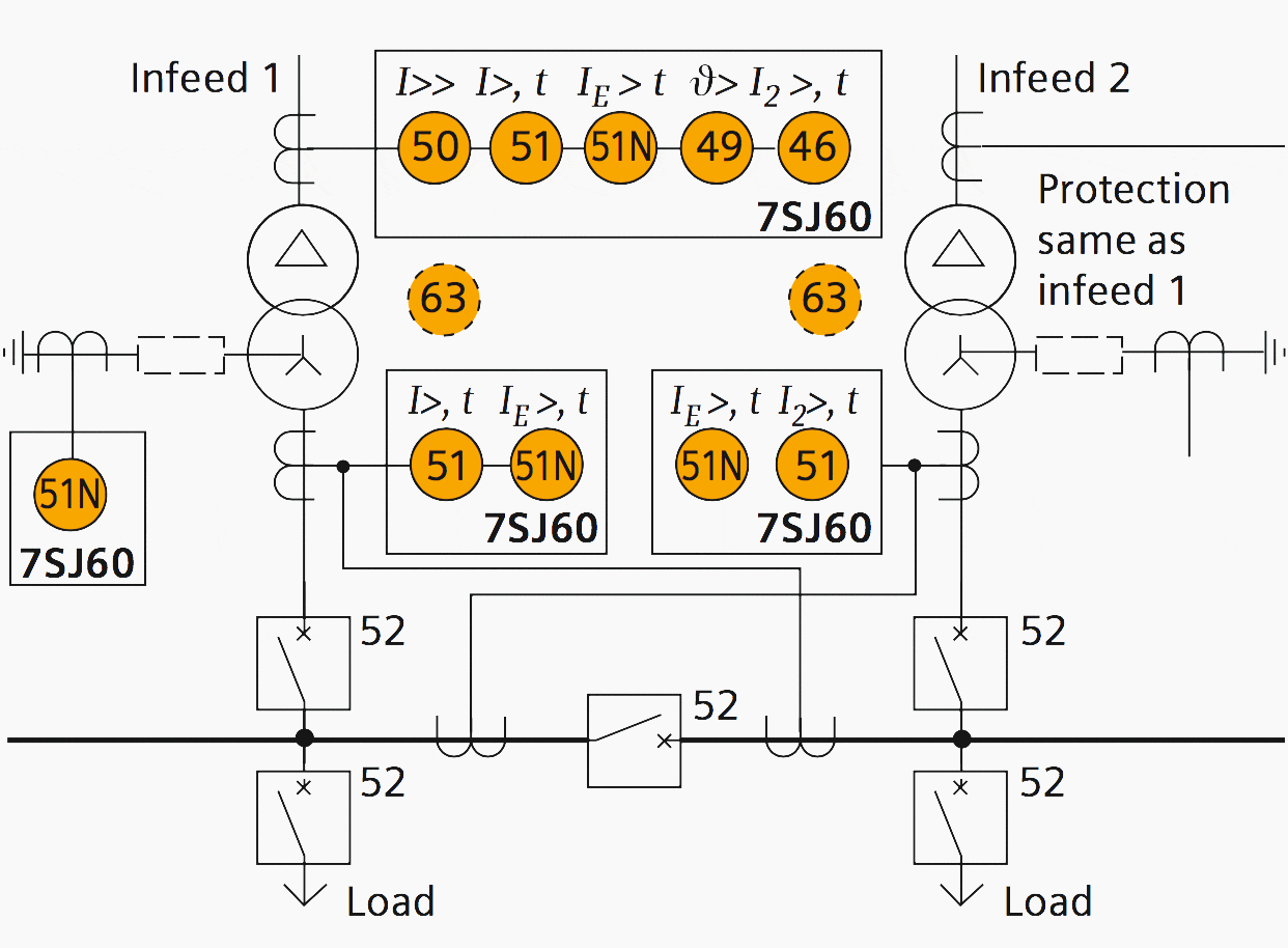
4. Parallel incoming transformer feeders
The directional functions 67 and 67N do not apply for cases where the transformers are equipped with the transformer differential relays 87T.
5. Parallel incoming transformer feeders with bus tie
Overcurrent relay 51, 51N each connected as a partial differential scheme. This provides simple and fast busbar protection and saves one time-grading step.
6. Three-winding transformer
The zero-sequence current must be blocked before entering the differential relay with a delta winding in the CT connection on the transformer side with earthed star-point. This is to avoid false operation during external earth faults (numerical relays provide this function by calculation).
Restricted earth-fault protection (87T) is optional. It provides backup protection for earth faults and increased earth-fault sensitivity (about 10 % IN, compared to about 20 to 30 % IN of the transformer differential relay). Separate class × CT- cores with equal transmission ratio are also required for this protection.
High impedance and overcurrent in one 7SJ61.
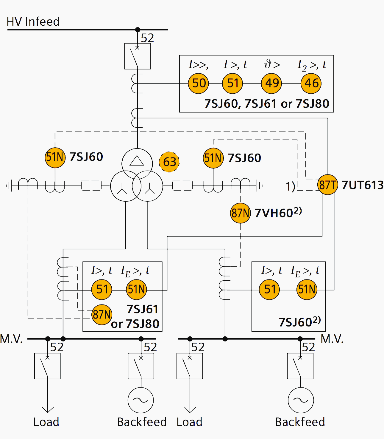
General notes //
In this example, the transformer feeds two different distribution systems with cogeneration. Restraining differential relay inputs are therefore provided at each transformer side.
If both distribution systems only consume load and no through-feed is possible from one MV system to the other, parallel connection of the CTs of the two MV transformer windings is admissible, which allows the use of a two-winding differential relay (7UT612).
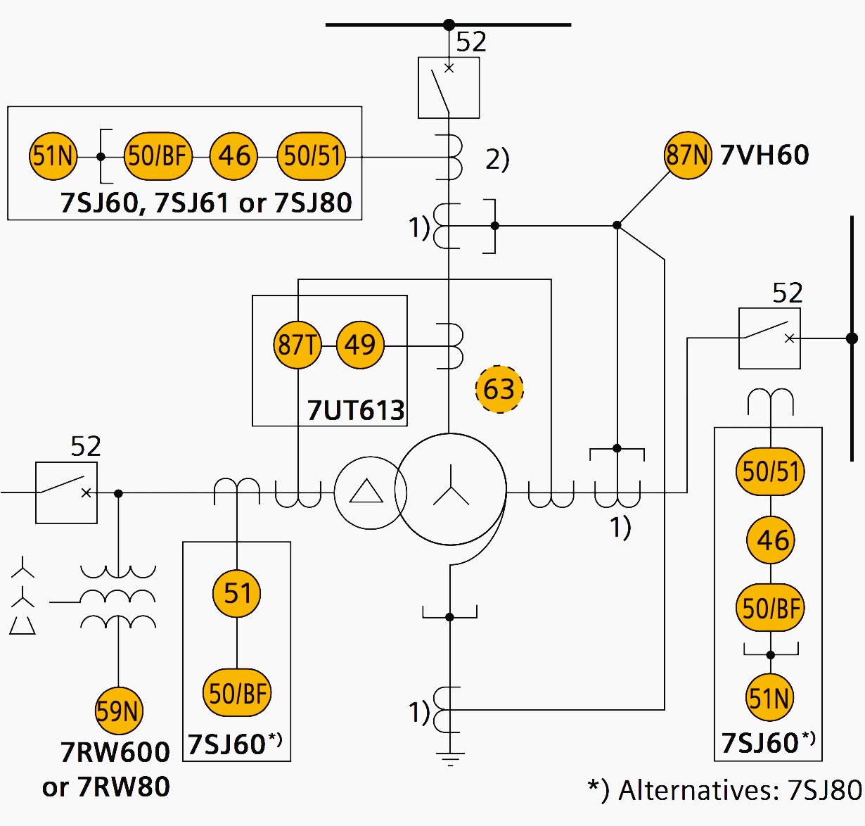
7. Autotransformer
87N high-impedance protection requires special class × current transformer cores with equal transformation ratios.
The 7SJ60 relay can alternatively be connected in series with the 7UT613 relay to save this CT core.
General note //
Two different protection schemes are provided: 87T is chosen as the low-impedance three-winding version (7UT613). 87N is a 1-phase high-impedance relay (7VH60) connected as restricted earth-fault protection.
In this example, it is assumed that the phase ends of the transformer winding are not accessible on the neutral side, that is, there exists a CT only in the neutral earthing connection.
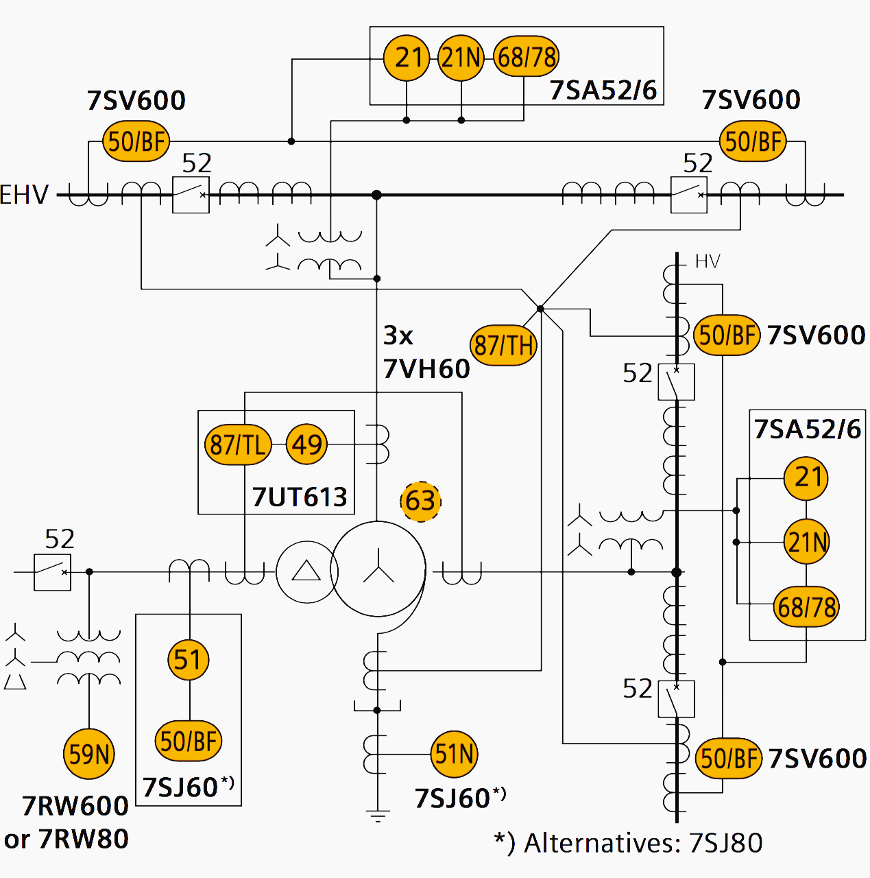
8. Large autotransformer bank
The transformer bank is connected in a breaker-and-a-half arrangement. Duplicated differential protection is proposed:
- Main 1: Low-impedance differential protection 87TL (7UT613) connected to the transformer bushing CTs.
- Main 2: High-impedance differential overall protection 87TL (7VH60). Separate class × cores and equal CT ratios are required for this type of protection.
Backup protection is provided by distance protection relay (7SA52 and 7SA6), each “looking” with an instantaneous first zone about 80 % into the transformer and with a time-delayed zone beyond the transformer. The tertiary winding is assumed to feed a small station supply system with isolated neutral.
Reference // Protection, Substation Automation, Power Quality and Measurement by Siemens
Related electrical guides & articles


Edvard Csanyi
Hi, I'm an electrical engineer, programmer and founder of EEP - Electrical Engineering Portal. I worked twelve years at Schneider Electric in the position of technical support for low- and medium-voltage projects and the design of busbar trunking systems.I'm highly specialized in the design of LV/MV switchgear and low-voltage, high-power busbar trunking (<6300A) in substations, commercial buildings and industry facilities. I'm also a professional in AutoCAD programming.
Profile: Edvard Csanyi

Thank you very much
The content is too much to grasp in one go .
Better to hvae discsuued case by acse showing the fault occurence and related operatins . Otherwise , it appears as Text book content
Thanks again
.
Appreciate the effort and the information
I like it.
i am an electrical engineer i would love to be receiving your news letters