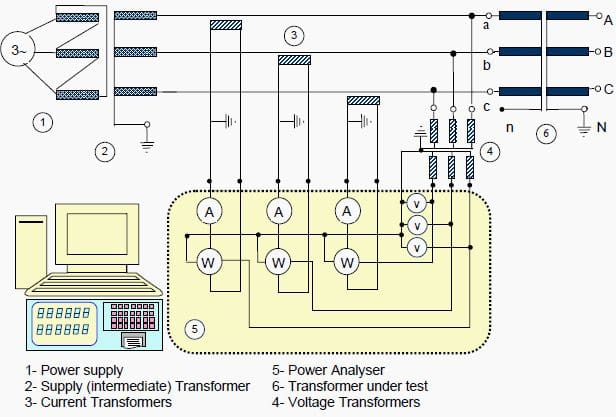
Introduction to test
The no-load losses are very much related to the operational performance of a transformer. As long as the transformer is operated, these losses occur. For this reason, no load losses are very important for operational economy. No-load losses are also used in the heating test.

The no-load loss and current measurements of a transformer are made while one of the windings (usually the HV winding) is kept open and the other winding is supplied at the rated voltage and frequency.
During this test the no-load current (Io) and the no-load losses (Po) are measured.
The measured losses depend heavily on the applied voltage waveform and frequency. For this reason, the waveform of the voltage should be very sinusoidal and at rated frequency.
Normally, the measurements are made while the supply voltage is increased at equal intervals from 90% to 115% of the transformer rated voltage (Un) and this way the values at the rated voltage can also be found.
No-load losses and currents
The no-load losses of a transformer are grouped in three main topics:
- Iron losses at the core of the transformer,
- Dielectric losses at the insulating material and
- The copper losses due to no-load current.
The last two of them are very small in value and can be ignored.
So, only the iron losses are considered in determining the no-load losses.
Measuring circuit and performing the measurement

In general according to the standards, if there is less than 3% difference between the effective (U) value and the average (U’) value of the supply voltage, the shape of the wave is considered as appropriate for measurements.
During measurements, the supply voltage U´ is supplied to the transformer by the average value voltmeter. In this way, the foreseen induction is formed and as a result of this, the hysteresis losses are measured correctly. The eddy-current losses should be corrected according to equation below.
Pm = P0 · (P1 + k · P2)
Pm: Measured loss
P0: No-load losses where the voltage is sinusoidal
Here: P0 = Ph + PE = k1 · f + k2 · f2
k = [ U / U’ ]2
P1: The hysteresis loss ratio in total losses (Ph) = k1 · f
P2: The eddy-curent loss ratio in total losses (PE) = k2 · f2
At 50 Hz and 60 Hz, in cold oriented sheet steel, P1 = P2 = % 50. So, the P0 no-load loss becomes:
Po = Pm / (P1 + k · P2) where P1 = P2 = 0,5
According to IEC 60076-1: Pm = P0 · (1 + d) where d = [ (U’ – U) / U’ ]
Before the no-load measurements, the transformer might have been magnetised by direct current and it’s components (resistance measurement or impulse tests).
For this reason, the core has to be demagnetised. To do this, it has to be supplied by a voltage value (increasing and decreasing between the maximum and minimum voltage values for a few minutes) higher than the rated voltage for a certain time and then the measurements can be made.
The no-load currents are neither symmetrical nor of equal amplitude in three phase transformers. The phase angles between voltages and currents may be different for each of three phases.
For this reason, the wattmeter readings on each of the three phases may not be equal. Sometimes one of the wattmeter values can be 0 (zero) or negative (-).
Resource: Transformer Tests – BEST Transformers


Why required to conduct the transformer no-load test at 90%, 100% and 115% of rated voltage. What is the significance of the 90% and 115%? From this data what we are interpreting?
Sir why transmission are done in 11,22,33,132,220kv why this odd number of multiple of 11.
I can answers above, 11,22,33,132,220 these depends on vector group use in transforming devices
Hi sir,
In your connection scheme, The LV winding Neutral (n) of the tested transformer is not wired but the the HV winding Neutral (N) is grounded. According to the IEC 60076-1 standards, “When a three-phase transformer is tested, the voltages shall be measured between line terminals, if a delta-connected winding is energized, and between phase and neutral terminals if a YN or ZN connected winding is energized.”. Can you please explain why you left the The LV winding Neutral (n) not connected and why you grounded the HV winding Neutral (N)?
I think that for a Four-Wire Wye connected tested transformer, we should connect the LV winding Neutral (n) to the neutrals of the PT primaries neutral and we can ground them together.
The neutrals of the PT secondaries connected to the Neutral port of the Analyser can be grounded (the neutral Port and the ground Port of the Analyser are connected together).
I will be so grateful if i get a feedback from you.
Thanks a lot and have a nice day
Sir please tell the clear difference between the no load test and harmonics test on no load conditions of distribution transformers. Whether the harmonics measurements can be made on no load or not??
Sir,
Why the wire size of the fusewire in structure is so small?
How can it possible to conduct high current?
Good morning
IA from Egypt . As electric manager of of the iron and steel Co
My point that we have 220kv/22.5 kv tr. 80 MIA had faced external School from the load side .trpped by different. ; boh. And so protection.
My question is the supplier need to do the following tests sc impedance . No load losses with reduced voltage . We need your opinion and support
Que nivel de armónicos se generan en los inversores de DC AC utilizados en la generacion fotovoltaica y se esto incide al inyectar esta energía en un red de distribución electrica convencional, el nivel de armónicos se incremente en la misma????