
Estimated Study Time: 5 minutes
Calculating Load Loss Values
Measurement is made to check transformer windings and terminal connections and also both to use as reference for future measurements and to calculate the load loss values at reference (e.g. 75ºC) temperature.
Measuring the winding resistance is done by using DC current and is very much dependent on temperature.
Temperature correction is made according to the equations below:

R2 – winding resistance at temperature t2,
R1 – winding resistance at temperature t1
Because of this, temperatures must be measured when measuring the winding resistances and temperature during measurement should be recorded as well.
The measuring current can be obtained either from a battery or from a constant (stable) current source. The measuring current value should be high enough to obtain a correct and precise measurement and small enough not to change the winding temperature.
In practice, this value should be larger than 1,2 x I0 and smaller than 0,1 x IN, if possible.
A transformer consists of a resistance R and an inductance L connected in serial. If a voltage U is applied to this circuit;
The value of current measurement will be :

Here, the time coefficient depends on L/R ratio.
As the measurement current increases, the core will be saturated and inductance will decrease. In this way, the current will reach the saturation value in a shorter time.
After the current is applied to the circuit, it should be waited until the current becomes stationary (complete saturation) before taking measurements, otherwise, there will be measurement errors.
Measuring circuit and performing the measurement
The transformer winding resistances can be measured either by current-voltage method or bridge method. If digital measuring instruments are used, the measurement accuracy will be higher.
Measuring by the current-voltage method is shown in figure 1 below:

In the current – voltage method, the measuring current passing through the winding also passes through a standard resistor with a known value and the voltage drop values on both resistors (winding resistance and standard resistance) are compared to find the unknown resistance (winding resistance).
One should be careful not to keep the voltage measuring voltmeter connected to the circuit to protect it from high voltages which may occur during switching the current circuit on and off.
When the currents flowing in the arms are balanced, the current through the galvanometer will be zero. In general, if the small value resistors (e.g. less than ≤1 ohm) are measured with a Kelvin bridge and higher value resistors are measured with a Wheatstone bridge, measurement errors will be minimised.

The resistance measured with the Kelvin Bridge:

The resistance measured with the Wheatstone Bridge:
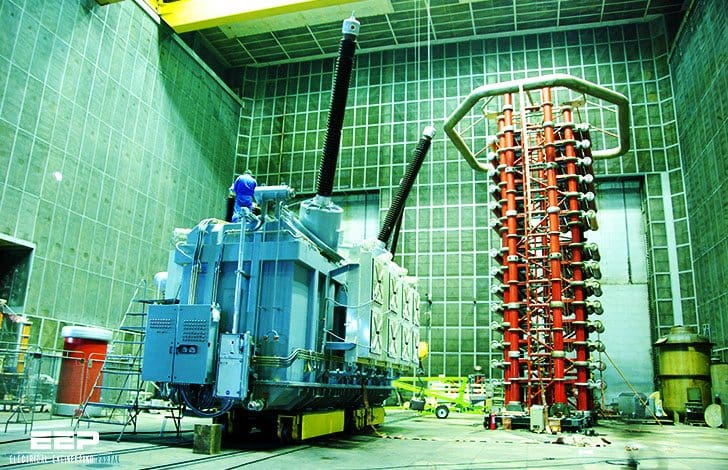
![]()
BEST Transformers laboratory

BEST Test laboratory is equipped with the most advanced testing facilities and is capable of conducting all tests required by IEC standards except short circuit mechanical withstand test, conducted in an independent international laboratory, CESI-Italy.
Tests performed on the transformers can be classified as follows:
Tests during manufacturing, routine tests, type tests, special tests, acceptance tests, site tests, defect analysis / identification and tests before maintenance.
Resource: BEST Transformer – Tests (BALIKESİR ELEKTROMEKANİK SANAYİ TESİSLERİ A.Ş.)
Related electrical guides & articles


Edvard Csanyi
Hi, I'm an electrical engineer, programmer and founder of EEP - Electrical Engineering Portal. I worked twelve years at Schneider Electric in the position of technical support for low- and medium-voltage projects and the design of busbar trunking systems.I'm highly specialized in the design of LV/MV switchgear and low-voltage, high-power busbar trunking (<6300A) in substations, commercial buildings and industry facilities. I'm also a professional in AutoCAD programming.
Profile: Edvard Csanyi

The picture is made in HV ICMET Romania
Given a transformer of rating as 100 kVA, 11/415-kV. delta star connected 50Hz.%Impedance of 4.66. Full primary and secondary current of 5.25/133.34 Amps. How can I obtain the primary and secondary resistance and inductance value?
resistance per winding = 1.5 * measured value…..my question is what is 1.5 and where it comes?
I have some questions regarding the reference temperature.
1.Why in IEEE the reference temperature is 75deg C and in IEC its 85deg C.
2.Why the reference cannot be one single temperature reference.
3.And why these temperature were chosen to be the reference temperature. Why not the other temperatures ( say 50deg C or 95deg C ) ?
Thank you….
In the field of solar flares inducing less than one Hz (call it DC) at 200 volts and a one ohm winding resistance, would not a 25 kVA transformer burn up.
Once the DC test is done with little bit high current for accuracy, sometimes saturated core will generate hormonics( 2nd, 27th) when rated voltage applied to take into service, causing protection relays to operate. … is there any method to reduce the saturation of the core…. One thing we did in the field was kept the transformer in normal tap for many hours, till the humming sound become normal.
Can u give pdf on the various losses in a transforme and a DC machines .variying with constant n variable losses
can you say how can i test the delta side of power transformer by current-voltage method . pls help me soon!
Please, Could You tell me what standard describes this test?