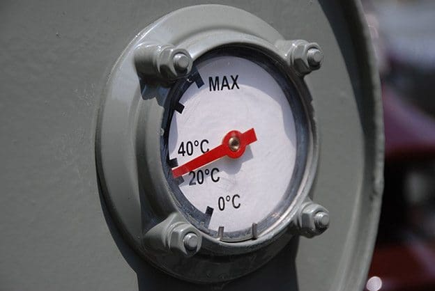
Temperature controls are required in order to turn on and off the cooling equipment. These controls are usually combined with a visible dial-type gauge that measures ‘winding temperature’.
This is really a misnomer because the gauge does not actually contact the winding.
Instead, it measures the top oil temperature plus a temperature gradient produced by a small heater surrounding the thermometer bulb. This heater is connected to a current transformer on one of the phases of the secondary leads, so as the secondary load increases, so does the current through the heater resistance.
The heater then becomes a mimic of the actual transformer winding with the winding temperature gauge measuring a temperature that is roughly equivalent to the true winding temperature.
In addition to (or instead of ) the winding temperature gauge, most transformers have an oil temperature gauge that measures the actual top oil temperature. The difference in temperature between the winding temperature gauge and the top oil temperature gauge is one indication of how heavily the transformer is loaded.
One example of this was a case of an OA cooling class transformer operating with a very high oil temperature. Further investigation revealed that a leak in the radiator had caused the oil level to drop below the radiator inlet, resulting in a virtual total loss of cooling. In other cases, investigations of elevated transformer temperatures have revealed blocked coolers and malfunctioning cooler controls.
An oil level gauge is required so that the correct oil level can be maintained. There is usually a mark on the gauge that indicates the 25°C level, which is the proper oil level at that temperature. Maintaining the proper oil level is extremely important because if the oil level falls below the level of the radiator inlet, flow through the radiator will cease and the transformer will overheat.
A very low oil level can expose energized and current-carrying components that are designed to operate in oil and could result in overheating or an electrical flashover. If the oil level is too high, it could cause over pressurization when the oil expands.

If the transformer is equipped with a constant-pressure nitrogen oil preservation system, then pressure gauges are included to measure the pressure of the gas blanket and the nitrogen in the make-up bottle.
Transformers that have a gas blanket over the oil in the main tank usually come equipped with pressure gauges. On random inspections, a sealed-tank unit should have a slight positive or a slight negative pressure. If the pressure gauge consistently records zero pressure under all loading and temperature conditions, this is an indication that the transformer tank has a leak, allowing it to ‘breathe‘.
This condition must be taken seriously and fixed, because a transformer that breathes is probably contaminated with moisture.
Reference: Power Transformers Principles and Applications – John J. Winders, Jr.


We are looking for
Transformer Oil Temperature Gauge 1-120 Degree C, Length 4.5 meter
Qty: 2 EA
Is there any effect if the ambient temperature is to low? In our case the oil level alarm triggered during 5 deg to 10 deg.
What should be the level of oil transformer? how it can be continuously maintained for the years?
By volume how much the transformer oil contracts during temperature reduction in 10 deg from ambient.
Is there any way in which the winding hot spot temperature be determined by correlating it with the given ambient and top oil temperature of the transformer? Thank you.
what is the name of transformer oil and its density?
What should be the order of oil, hv and lv winding temperature in a power transformers?
The two transformer are connected to one(1) MV Switchgear or feeder.The old transformer has the following protections feature:
1.Oil Thermometer
2.Oil Level Relay
3.Buchholz Relay
4.Winding Temperature Indicator
But,the new transformer has an additional protection feature as the following:
5.Pressure Relief Device
6.Rapid Pressure Rise Relay
7.LV Current Transformer
Thank you and best regards.
It is possible to parallel the protection of the two transformers with same feeder?
i want to know about how we choose an MCB/MCCB for a given load requirement/load current/load HP.how could we choose that?????
Chosing of MCB/MCCB depands following things
1. The nominal current of transformer .. Or load against it
2. In a thumb rule you have to chose the rating of MCcB 1.25 times of that calculate current
3. You also have to calculated the prospective Short circuit current of your distribution that mainly depends on transformer rating its impedance and the distance between load and transforms. Thus u can chose the right breaking capacity
4. The other things you need to know the coordination of upstream and down steam breaker so to protect unexpected tripping
5.last thing you need to chose the right curved breaker like what will be its instant trip or long time trip … U have to define it by setting or chose from the catalogue
show circuit diagrams with explanations
Please Explain in detail, How the thermal imaging in winding Temperature Indicator works exactly? How this is occurring in a transformer? If a CT is mounted on the secondary, then the current can flow through a heater coil to show the exact winding temperature…then why the temperature probe is mounted on the transformer??? Please explain me in detail….Thank you…
How about the pressure gauge indicates a vacuum reading, what does it mean?