
Estimated Study Time: 16 minutes
Voltage Regulation Equipment
Almost all transformers incorporate some means of adjusting their voltage ratio, by adding or removing tapping turns. This adjustment may be made by an on-load tap-changer, or by means of an off-circuit tap-changer, or by the selection of bolted link positions with the transformer disconnected and grounded.
 Transformer Voltage Regulation (Off-Load Tap Changer, On-Load Tap Changer and AVR) - photo credit: ABB
The degree of sophistication of the system of tap selection depends on the frequency with which it is required to change taps and the size and importance of the transformer.
Let’s discuss now the following ways of voltage regulation. First two are performed on the transformer, while third way is on the relay system in the power substation.
1. Off Circuit Tap Changer
The off-circuit tap-changer is of rather simple design, giving connection to a selected tap in the winding. As the name says it is designed only to be operated only when the transformer is de-energised.
The contact pressure may occur to be retained by some kind of spring arrangement and then some vibration is possible.
Ultimately a runaway situation is reached and the transformer will probably trip on gas actuated protection or worse – a step short circuit occurs.
To avoid this it is vital that the tap changer is operated, off circuit, through its complete range a few times during regular routine maintenance to wipe the contact surfaces clean before returning it back to the selected tapping.
Of course the same advice is valid if an on-load tap-changer is left in service but without operation for a long period.
2. On Load Tap Changer (OLTC)
The on-load tap-changer has to provide uninterrupted current flow during the transition operation from one tap to the other. The current flow must be maintained uninterrupted without partial short-circuiting of the tapped winding.
As early as between 1905 and 1910 arrangements were introduced for changeover between tappings of the transformer without interruption of supply.
The operation of an on-load tap-changer can be understood by two identifiable functions.
It implies a switching device that transfers the throughput power from one tap of the transformer to an adjacent one. During this operation the two taps will be connected through fitted transition impedance. In this phase the two taps will share the load current.
Thereafter the connection to the former tap will be interrupted and the load has been transferred to the new tap. The device that performs this switching is called diverter switch.
The connections to the two taps that involve the diverter switch are maybe transferred one position along the series of physical taps of the regulating winding for each operation. This is the tap selector function. The tap selection is conducted without any current rupture.
An alternative to the principle with fast acting switching sequence and resistors is to use reactor. In a reactor type tap-changer it is instead more difficult to break the circulating reactive current and this will rather limit step voltages but it will works well at relatively high currents.
This compared to a fast operating resistance tap-changer, which can handle higher voltage but not high current.
This leads to reactor tap-changer being usually located on low voltage of the transformer while resistance tap-changer will be connected on the high voltage side.
In a reactor type tap-changer the losses in the mid-point reactor due to the load current and the superimposed circulating current between the two involved tap is small and the reactor can be left permanently in circuit between them.
This provide an intermediate step between two taps and this gives twice as many working positions as the number of taps in the winding.
From the 1970.s tap-changers with vacuum breakers have been available. Vacuum breakers have low contact erosion and this gives tap-changers with increased number of operation between necessary services. The design is however generally becoming more complex.
Also experimental designs of tap-changers where the changeover function is effectuated by power semi-conductor elements have been in the market. These designs also with the aim of reduced services intervals.
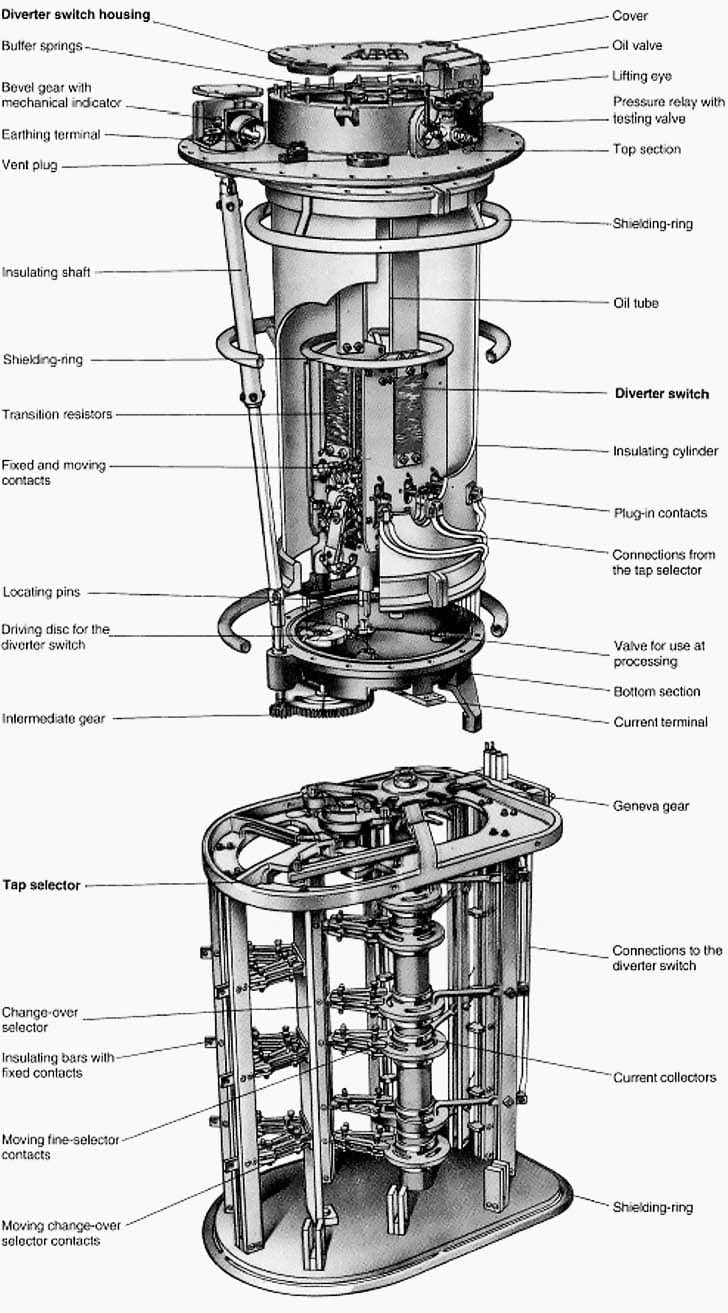
In resistor type tap-changers the diverter switch is enclosed in a container with oil separated from the oil in the transformer. The oil in this container will be very contaminated in due course and must be kept separate from the oil system of the transformer itself and should also have a complete separate conservator volume with its own breather.
The selector contacts never break any current and can be situated in the transformer oil itself.
When the free arm has found its position the diverter switch transfer the load over. The operating cycles of the diverter is shown in Figure 1 Flag cycle.
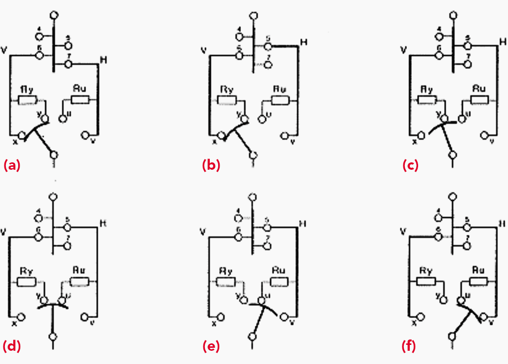
Flag cycle arise from the rectangular vector diagram of transformer output voltage when moving from one tapping to an adjacent one.
- (a) The tap-changer has come from tap 7 and is presently connected at tap 6 and shall connect to tap 5.
- Selector arm H moves from tap 7 to tap 5.
- The diverter switch engages the resistor, the load current from tap 6 go through Ry.
- Step 5 and 6 are short-circuited through Ry plus RU, the resistors are dimensioned to prevent a short circuit of the loop but also to keep acceptable voltage disturbance. The circulating current is in the range as the rated load current.
- The diverter breaks the connection with tap 6 and load current comes from tap 5 through R.
- Changeover resistor is bypassed and connection direct to step 5 is established.
Tap-changers for lighter duty, moderate voltages to earth and over the regulating range are of some manufacturers built in a simpler manner.
In such tap-changers both the selection and switching are carried out on the same contact. The intermediate contacts and the transition resistor are mounted on one the moving arm. The arm moves in rapid jerks and passes the series of contacts that are installed along a circular arc when going from tap contact to the next.

Also in this type the cycle consequently involves an interruption of power, which entails arc and contact erosion and the tap-changer housing has to be closed from the transformer oil. Tap changers of such design is referred to as selector switch type.
In such a single resistor type tap-changer the load current and the resistor circulating current have to be arranged to be subtractive, which dictates the power flow direction through the transformer or at least reduced rating with reverse power flow.
The single resistor type is named to follow a pennant cycle.
The terms arise from the appearance of the vector diagram showing the change in output voltage of the transformer when moving from one tapping to the adjacent one. In same manner the double resistor type is named to follow a flag cycle. The flag cycle gives no restriction to power flow direction.

When only limited regulating range, up to 10% of nominal value, is required it is common to arrange the regulating winding for linear regulation. This means that the induced voltage in the regulating winding is added to the voltage in the main winding.
The third arrangement is a coarse-fine regulation where the voltage regulation function is split into two winding, one for the coarse step and one for the fine steps.
Some comparisons of the three arrangements:
- All three need the same total number of turns in the windings.
- Linear need double number of steps in a fine winding compared to plus-minus or coarse-fine which is a disadvantage when larger regulation range. Both due to the design of the winding and complexity of the tap-changer.
- Plus minus need one separate winding less compared to coarse-fine.
- Coarse-fine give less load losses in the minus part of the regulation range compared to plus minus.
- The plus-minus tap-changer and the coarse-fin tap-changer are almost equal; the selector in both contains a changeover selector.
There are several different ways of arranging the regulation with regard to the size and the location of the regulation winding. A regulating winding is difficult and expensive to manufacture and it represents an insulation risk because those parts that are not connected in circuit will oscillate freely when the transformer is subjected to over voltage surges.
There is every reason to make the regulating range and the regulating winding as small as possible.
Tap-changers are provided with counter that indicated the number of executed changeover operations, and of course with an indicator for the actual tapping that is connected. It is often required that this indication shall also be remotely available in the control room.
For the driving of the tap-changer there is a need for auxiliary motor power and in addition auxiliary voltages for control and monitoring circuits and indicators.
The tap-changer is a moving mechanism and actually they are the only vital parts of the transformer that do move and it should be serviced regularly.
Automatic Voltage Regulation (AVR)
The tap-changer is installed to meet voltage variation in the systems connected to the transformer. It is not certain that the goal would be to maintain a constant secondary voltage at all times.
However, certain functions for coordination between different transformers in the same station are part of the tap-changer technology. When different transformers are directly parallel connected their tap-changer should move in step with each other. This is arranged in such a way that one is wired as a master and the other as a slave.
Absolutely simultaneous operation will not be achieved but there is a small interval with circulating current between the two transformers. This is however without any practical importance.
Reference // Transformer handbook by ABB
Related electrical guides & articles


Edvard Csanyi
Hi, I'm an electrical engineer, programmer and founder of EEP - Electrical Engineering Portal. I worked twelve years at Schneider Electric in the position of technical support for low- and medium-voltage projects and the design of busbar trunking systems.I'm highly specialized in the design of LV/MV switchgear and low-voltage, high-power busbar trunking (<6300A) in substations, commercial buildings and industry facilities. I'm also a professional in AutoCAD programming.
Profile: Edvard Csanyi

Greeting
I am an electrical engineer and a permanent follower to you and this is my Gmail
why Rectifier transformer has more taps, around 94 taps where as Generating TXF has less number of taps around 10