
Estimated Study Time: 5 minutes
3 rules for parallel transformers
The following rules must be obeyed in order to successfully connect two or more transformers in parallel with each other:
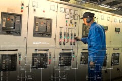
 Matching transformers for parallel operation (photo credit: ABB)
- The turns ratios of all of the transformers must be nearly equal.
- The phase angle displacements of all of the transformers must be identical.
- The series impedances of all transformers must be nearly equal, when expressed as ‘%Z‘ using the transformer impedance base.
The first two rules are required so that the open-circuit secondary voltages of the transformers are closely matched in order to avoid excessive circulating currents when the parallel connections are made. The last rule is based on the fact that for a given voltage rating and %Z, the ohmic impedance of a transformer is inversely proportional to its KVA rating.
Therefore, transformers with different KVA ratings can be successfully operated in parallel as long as their %Z values are all approximately the same.
Example of parallel transformers and loud BANG!
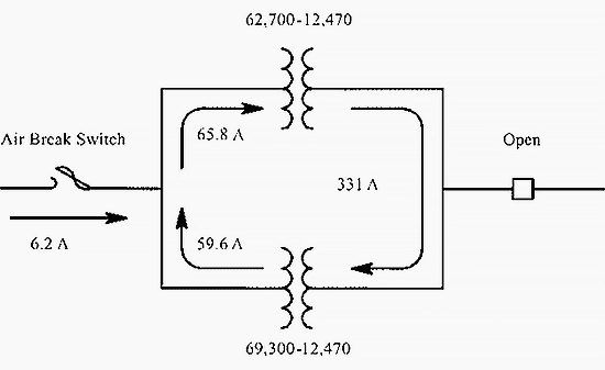
Two three-phase 10,000 KVA 66,000∆ – 12,470Y volt transformers were in parallel operation in a substation. The primaries of the two transformers are connected to a 66 kV transmission line through a single air break switch. This switch is designed to interrupt magnetizing current only, which is less than 1 A.
The transformers were being removed from service and the secondary loads had been removed. A switchman then started to open the air break switch, expecting to see a small arc as the magnetizing current was interrupted.
Instead, there was a loud ‘BANG’ and there was a ball of flame where the air break switch contacts had vaporized. Something was obviously wrong. Upon closer inspection, it was revealed that the two transformers had been set on widely different taps:
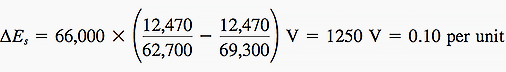
The first transformer was on the 62,700 V primary tap and the second transformer was on the 69,300 V primary tap. Both transformers had a 7% impedance. Because the turns ratios were unequal, a circulating current was set up even without any secondary load. The open-circuit secondary voltage difference, assuming 66 kV at the transformer primaries, is calculated below.
The per-unit circulating current in the secondary loop is equal to ∆Es divided by the sum of the per-unit impedances of the two transformers //
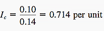
Converting Ic into amperes //
![]()
Since Ic flows in a loop in the secondary circuit, the current out of the secondary of the first transformer equals the current into the secondary of the second transformer. But since the turns ratios are not equal, Ic does not get transformed into equal and opposite currents at the primaries.
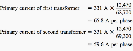
The net current through the air break switch, IAB, is the difference in the primary currents //
![]()
What actually happened?
The current through the air break switch supplies the Ic2Xs reactive losses of both transformers and therefore lags the primary voltage by 90°. The resulting current exceeded the interrupting rating of the switch, causing it to fail. The conditions described in this example are diagramed in Figure 1 above.
Related electrical guides & articles


Edvard Csanyi
Hi, I'm an electrical engineer, programmer and founder of EEP - Electrical Engineering Portal. I worked twelve years at Schneider Electric in the position of technical support for low- and medium-voltage projects and the design of busbar trunking systems.I'm highly specialized in the design of LV/MV switchgear and low-voltage, high-power busbar trunking (<6300A) in substations, commercial buildings and industry facilities. I'm also a professional in AutoCAD programming.
Profile: Edvard Csanyi

If I had two transformers connected in parallel (11000v/400v), one of them had a capacity of 500 KVA and the tab was placed at 2 (so the conversion ratio would become: 11250v/400v).
The second had a capacity of 1000 KVA and the tab was at 3 (normal operation: 11000v/400v)
The transformers were feeding the same one load (700 KW, 500 KVAR).
Both have the same voltage impedance (4%).
How will the load be distributed among them?
Hi Sir Good Day, will this be the same if the two power transformers came from two different sources with two different voltages, the one from 480V generator and the other from 4160V generator
Would feeder protection remain the same once you parallel transformers? Should extra protection be installed?
I leave a backup 10mVA transformer heated up but isolated because I fear a major fault on my plant’s feeders may take out both my main and backup transformers.
Thank you a lot , really good posts.
I have a question , what is the pourpose of having different types of connections like Dy5 or Dy7??
Thank you so much,
Your articles are really useful to so many of us
And the quality of the article is too good ,keep updated us,
In any means if I could support your service Please let me know
Best Regards / Cordialement,
Kittappa
.
Wow so you great thanks
Great discussion.
Thank you so much, I learn something new every day.
Dear Edvard Csanyi,
you are doing a great job.
Thanks to Edvard Csanyi .
Electrical Wikipedia