Transformer on-site checks
On-site inspection of the substation transformer usually exposes important condition changes and it initiates various suspicions that need to be investigated in detail. As with any other substation equipment, many things could go wrong during the transformer operation. For example, temperature indicators could stuck, or Buchholz relay’s mechanism could falsely detect faults or even oil pump failure.
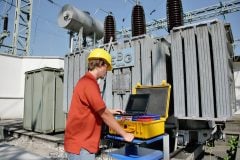
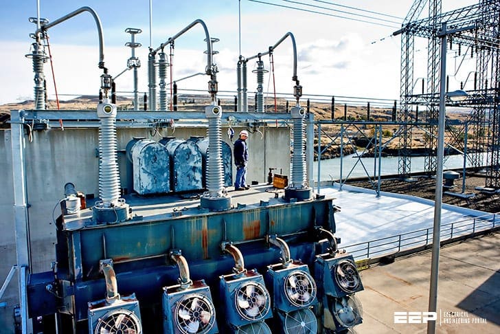
Not to speak of the oil leaks that can often indicate a potential for oil contamination, loss of insulation, or environmental problems. These are all very serious problems that substation maintenance staff must take care of very carefully when inspecting a transformer.
Such transformer inspection requires maintenance staff experienced in these techniques. Ok, let’s name these checks and try to shed some light on each of them.
Table of contents (or what you have to do):
- To check temperature indicators online
- To check temperature indicators offline
- To check conservator
- To check conservator breather
- To check nitrogen
- To check for oil leaks
- To check pressure relief device
- To check oil pumps
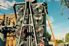
- To check fans and radiators
- To check Buchholz relay
- To check sudden pressure relay
- To check bladder failure relay
1. To Check Temperature Indicators Online
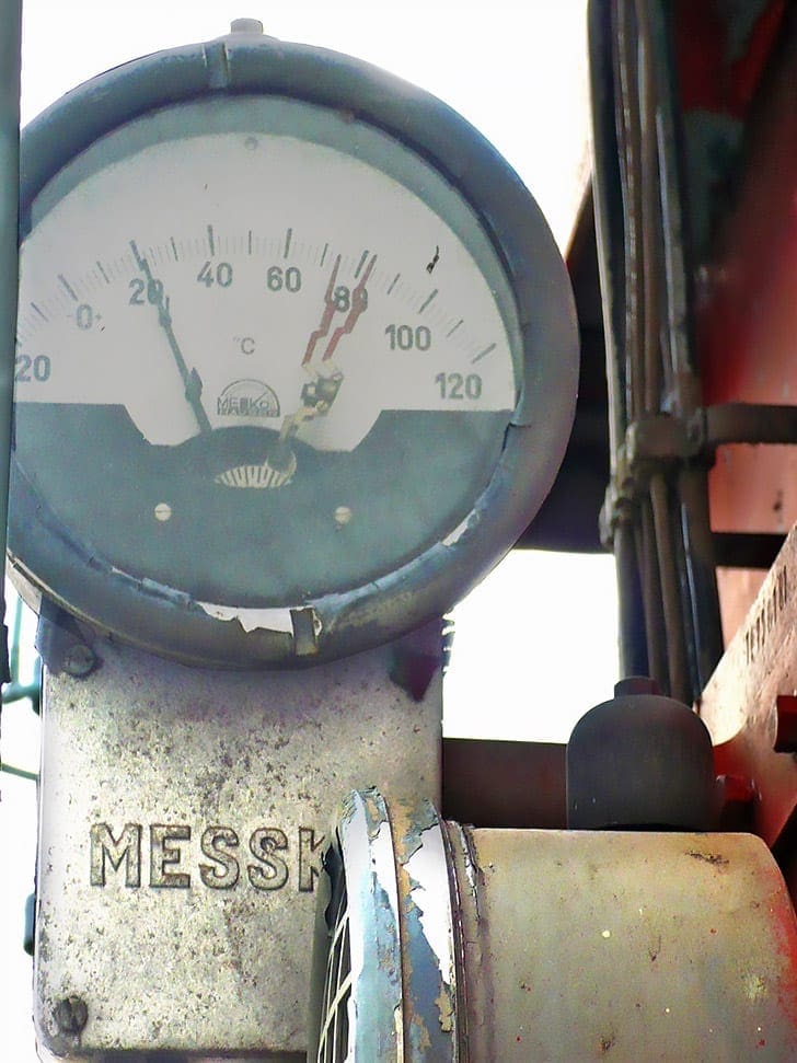
Check all temperature indicators while the transformer is online. The winding temperature indicator should be reading approximately 15 degrees above the top oil temperature. If this is not the case, one or both temperature indicators are malfunctioning.
Check the top oil temperature next to the top oil indicator’s thermowell with an infrared camera. Compare the readings with the top oil indicator. Reset all maximum indicator hands on the temperatures indicating devices after recording the old maximum temperature readings.
High temperature may mean overloading, cooling problems, or problems with windings, core, or connections.
Field testing has shown some of these indicators reading 15 °C to 20 °C lower than actual temperature.
This is hazardous for transformers because it will allow them to continuously run hotter than intended, due to delayed alarms and cooling activation. If thermometers are not tested and errors corrected, transformer service life may be shortened or premature failure may occur.


Go back to Table of Contents ↑
2. To Check Temperature Indicators Offline
When the transformer is offline and has cooled to ambient temperature, check the top oil and winding temperature indicators. Both should be reading the same. If not, one or both temperature indicators are malfunctioning.
Check the calibration according to the proper procedure. Also compare these readings with the indicated temperature on the conservator oil level indicator. All three should agree.
Go back to Table of Contents ↑
3. To Check Conservator
Check the oil level gauge on the conservator. See Figure 2 below. This gauge indicates oil level by displaying a temperature. Compare the indicated temperature on the conservator level gauge with the top oil temperature indicator. They should be approximately the same.
Calibrate or replace the conservator oil level indicator if needed, but only after checking the top oil temperature indicator.
With the transformer offline and under clearance, open the inspection port on top of the conservator and look inside with a flashlight. If there is a leak, oil will be visible on top of the diaphragm or inside the bladder. Reclose the conservator and replace the bladder or diaphragm at the first opportunity by scheduling an outage.


If there is no gas inside the Buchholz Relay, the transformer may be re-energized after bleeding the air out of the bladder failure relay. A DGA should be taken immediately to check for O2, N2, and moisture.
However, the transformer may be operated until a new bladder is installed, keeping a close eye on the DGAs. It is recommended that DGAs be performed every 3 months until the new bladder is installed. After the bladder installation, the oil may need to be de-gassed if O2 exceeds 10,000 ppm.
Check the desiccant in the breather often. Never let more than two-thirds become discolored before renewing the desiccant. All efforts should be made to keep the oxygen level below 2,000 ppm and moisture as low as possible.
Go back to Table of Contents ↑
4. To Check Conservator Breather
Check the dehydrating (desiccant) breather for proper oil level if it is an oil type unit. Check the color of the desiccant and replace it when approximately one-third remains with the proper color.
See Figure 3 for an oil type desiccant breather.
Notice the pink desiccant at the bottom of the blue indicating that this portion is water saturated. Notice also that oil is visible in the very bottom 1-inch or so of the unit. Many times, the oil is clear, and the oil level will not be readily apparent.


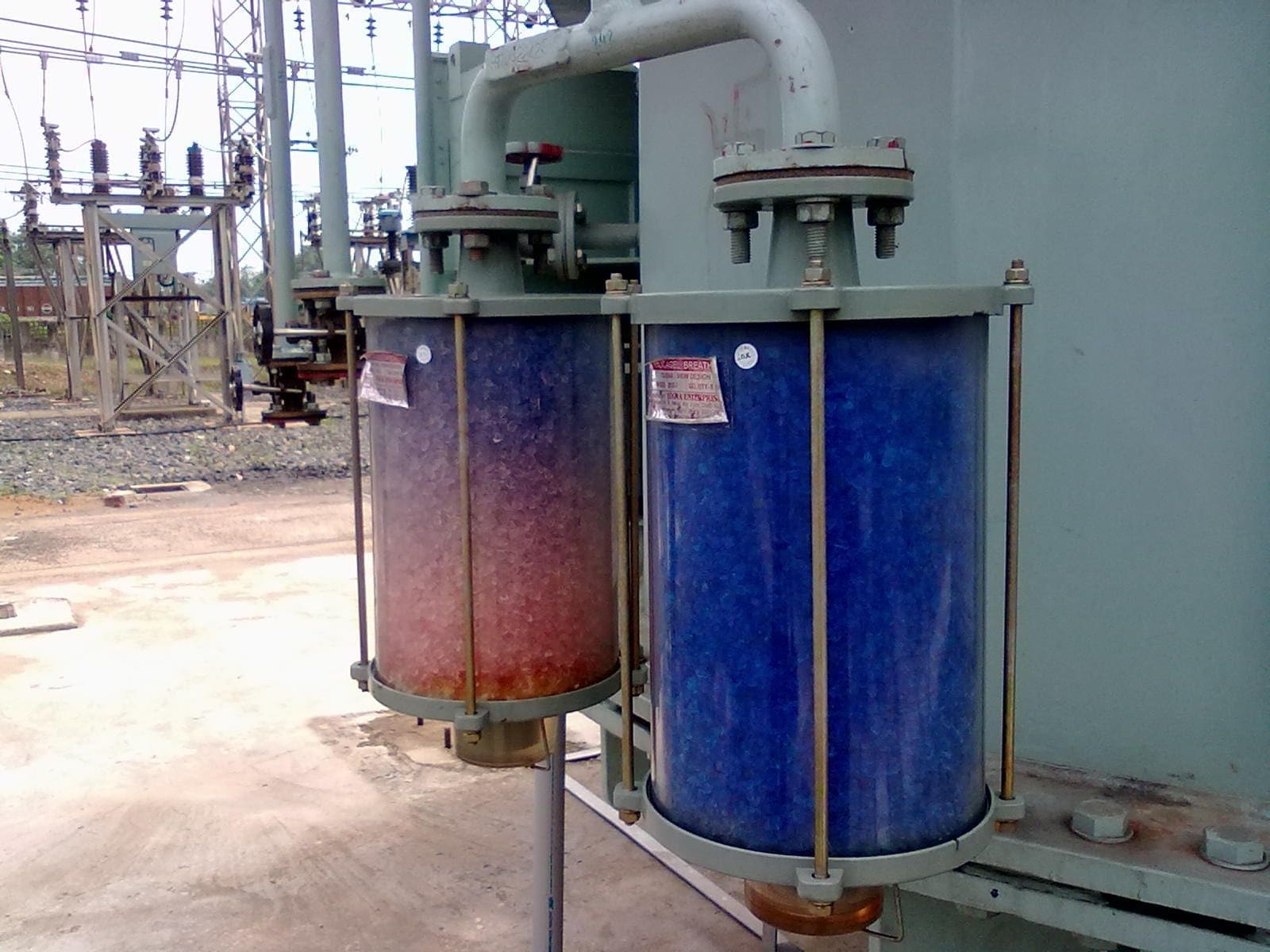
Normally, there is a thin line around the breather near the bottom of the glass. This indicates where the oil level should be. Compare the oil level with the level indicator line and refill, if necessary. Note the 1¼-inch pipe going from the breather to the conservator.
Small tubing (½ inch or so) is not large enough to admit air quickly when the transformer is de-energized in winter.
A transformer can cool so quickly that a vacuum can be created from oil shrinkage with enough force to puncture a bladder. When this happens, the bladder is destroyed and air is pulled into the conservator making a large bubble.
Go back to Table of Contents ↑
5. To Check Nitrogen System
If the transformer has a nitrogen blanket, check the pressure gauge for proper pressure. Look at the operators recording of pressures from the pressure gauge. If this does not change, the gauge is probably defective. Check the nitrogen bottle to insure the nitrogen is the proper quality.
Check for any increased usage of nitrogen which indicates a leak. Smaller transformers such as station service or smaller generator-step-up transformers may not have nitrogen bottles attached to replace lost nitrogen.
Be especially watchful of the pressure gauge and the operator’s records of pressures with these. The pressure gauge can be defective for years, and no one will notice. And that’s not good.


The gauge will read nearly the same and will not vary much over winter and summer or night and day. Meanwhile, a nitrogen leak can develop and all the N2 will be lost. This allows air with oxygen and moisture to enter and deteriorate the oil and insulation. Watch for increased oxygen and moisture in the DGA.
An ultrasonic and sonic leak detection instruments are usually used for locating N2 leaks.


Go back to Table of Contents ↑
6. To Check For Oil Leaks
Oil leak is very dangerous, especially if not spotted on time. What should maintenance staff do? They should check the entire transformer for oil leaks. Leaks usually develop due to gaskets wearing out, ultraviolet exposure or from expansion and contraction, especially after transformers have cooled, due to thermal shrinkage of gaskets and flanges.
Many leaks can be repaired by applying an epoxy or other patch. Flange leaks may be stopped with these methods using rubberized epoxy forced into the flange under pressure.
Very small leaks in welds and tanks may be stopped by peening with a ball-peen hammer, cleaning with the proper solvent, and applying a “patch” of the correct epoxy.


Experienced leak mitigation contractors whose work is guaranteed may also be employed. Some leaks may have to be welded. Welding may be done with oil in the transformer if an experienced, qualified, and knowledgeable welder is available.
If welding with oil in the tank is the method chosen, oil samples must be taken for DGA both before and after welding. Welding may cause gases to appear in the DGA and it must be determined what gases are attributed to welding and which ones to transformer operation.


Go back to Table of Contents ↑
7. To Check Pressure Relief Device
See Figure 8 showing a pressure relief device with the yellow indicating arm. With the transformer under clearance, check the pressure relief device indicating arm on top of the transformer to see if it has operated.
If it has operated, the arm will be in the up (vertical) position, and alarm and shutdown relays should have activated.
CAUTION!! – Do not re-energize a transformer after this device has operated and relays have de-energized the transformer, until extensive testing to determine and correct the cause has been undertaken.
Explosive, catastrophic failure could be the result of energization after this device has operated.


Go back to Table of Contents ↑
8. To Check Oil Pumps
The pump set is a single stage axial flow gland-less type, integral with the drive motor. It has been specifically designed for forced circulation of oil through the cooling system of large transformer and allows thermo-phonic flow. It is designed for flange mounting directly to the pipe circuit of transformers in either horizontal or vertical position. All the moving parts are completely enclosed and gasket thus permitting open air installation, without any need for protective cover. It is compact in design.
If the case of transformer that has oil pump(s), maintenance staff must check flow indicators and pump isolation valves to ensure oil is circulating properly.
Compare results with the full-load-current indicated on the motor nameplate. If the motor is reversed, the current will be much less than the nameplate full-loadcurrent.


Check oil pumps with a vibration analyzer if they develop unusual noises. Have the DGA lab check for dissolved metals in the oil and run a metal particle count for metals if the bearings are suspect. This should be done immediately, as soon as a bearing becomes suspect.
Bad oil-pump bearings can put enough metal particles into the oil to threaten transformer insulation and cause flashover inside the tank.
An explosive catastrophic failure of the transformer tank could be the result.


Go back to Table of Contents ↑
9. To Check Fans and Radiators
Maintenance staff must check and test all isolation valves at the tops and bottoms of radiators to ensure they are open. Inspect cooling fans and radiators for cleanliness and fans for proper rotation. Checking for dirty or damaged fan blades or partially blocked radiators is obligatory.
Also, it’s always a good practice to check if fans are reversed electrically (i.e., pulling air first through the radiators and then through the fan blades). This means the blades are rotating in warm air after it passes through the radiator which is much less efficient. Place a hand on the radiator opposite the fans.
Air should be coming out of the radiator against your hand.
Watch the blades as they rotate slowly when they are starting or stopping to determine which way they should be rotating and correct the rotation if necessary.


Go back to Table of Contents ↑
10. To Check Buchholz Relay
Inspect the isolation valve on the Buchholz relay to ensure it is open. With the transformer offline and under clearance, examine the Buchholz relay by lifting the window cover (center in Figure 12 below) and looking inside.
How it works? – If there is gas inside, the oil will be displaced, and the gas will be evident as a space on top the oil. If sufficient gas is found to displace the upper float, the alarm should be activated. The small valve at the top left is to bleed the gas off and reset the relay.
If a small amount of gas is found in this relay when the transformer is new (a few months after startup), it is probably just air that has been trapped in the transformer structure and is now escaping. There is little cause for concern.
A definite cause of the gas bubbles must be determined and corrected before re-energization of the transformer.


Go back to Table of Contents ↑
11. To Check Sudden Pressure Relay
An example relay is shown in the video below. The purpose of this relay is to alarm if there is a sudden pressure rise inside the tank. This relay is very sensitive and will operate if the pressure rises only a little.
Inspect the isolation valve to ensure it is open. With the transformer offline and under clearance, functionally test the sudden pressure relay by slowly closing the isolating valve. Leave it closed for a few seconds and reopen the valve very suddenly.
This should activate the alarm. If the alarm does not activate, test the relay and replace it with a new one if it fails to function.
Go back to Table of Contents ↑
12. To Check Bladder Failure Relay
On newer transformers, a bladder failure relay may be found on or near the conservator top on the oil side of the bladder. This relay is near the highest point of the transformer. Its purpose is to alarm if the bladder fails and admits air bubbles into the oil.
Of course, these gases should also show up in the DGA. However, DGAs are normally taken only once per year, and a problem may not be discovered before these alarms are activated.
If the bladder failure alarm is activated, place the transformer under clearance and check the Buchholz for gas as mentioned above.


Open the conservator inspection port and look inside with a flashlight to check for oil inside the bladder. Bleed the air/gas from the conservator using the bleed valve on top of the conservator. If the transformer is new and has been in service for only a few months, the problem most likely is air escaping from the structure.
With the transformer under clearance, open the inspection port on top of the conservator and look inside the bladder with a flashlight. If oil is found inside the bladder, it has developed a leak; a new one must be ordered and installed.
Go back to Table of Contents ↑
Sources:
- Transformer diagnostics by U.S. Department of the Interior Bureau of Reclamation
- Operation and Maintenance for Power Transformers – ABB’s User’s Manual
- Transformers: Basics, Maintenance, and Diagnostics by U.S. Department of the Interior Bureau of Reclamation
- Substation Transformer Installation, Operation, and Maintenance Instructions and Parts Replacement Information – Cooper Industries
- Sudden Pressure Protection for Transformers – A report to the Substation Protection Subcommittee of the Power System Relaying Committee of the IEEE Power and Energy Society
- Transformer Maintenance / Monitoring Seminar by Unifin
informations about transformer oils chemistry
can I use one neutral grounding resistor for four generators of 11KV 2200KVA
yes of course, but only a star center for parallel generators must be connected to ground via a contactor or on the switchboard since there is no wye point available for connection to ground, one must be created by artificial means.
This can be done with the grounding transformer