
Estimated Study Time: 46 minutes
Switchyard design
This article aims to shed some light on the so-called physical engineering activity in switchyard design in conjunction with some engineering computations. The physical layout engineering tackles the plot plan and SLD to optimize the area and coordinate with all related disciplines, such as protection and control, civil engineers, etc. This article also touches on the engineering process followed at the design stage and covers their links to the switchyard layout.
 The art of the transmission switchyard design: The physical layout engineering (Case study included)
A switchyard design methodology entails different stages that are so interrelated that mandate the so-called physical engineering. These stages are listed as follows:
- Site consideration
- Environmental consideration
- Interfacing considerations (i.e., telecommunication, water/sewer, gas, etc)
- Reliability consideration
- Operating consideration
- Safety consideration
- Maintenance consideration
Physical engineering produces or supervises the development of formal plans from which a substation can be constructed. These documents fulfill their primary role of establishing design and functional requirements. Also, they serve as a record of what was built, specified, or evaluated.
There are different types of drawings that are typically required for switchyard design:
- SLD-Switching
- SLD-Functional relaying
- Three-line diagram
- Electrical plot plan
- Site preparation
- Fence layout
- Electrical layouts
- Structure erection diagrams
- Foundation layouts
- Grounding layout
- Conduit layout
- Control house: Architectural, equipment, layout, lighting, etc.
- Station service diagrams AC and DC
- Cable and conduit lists
- Bills of material (BOM)
- Drawing list
- Control panels
- Schematic and detailed wiring diagrams
The switchyard equipment sizing and specifications relationship are mentioned. Then, different switchyard systems are elaborated, including a grounding system, lightning arrestor, protection and control, and switchyard plan layout.
- Engineering Studies
- Switchyard Layout Design
- Case Study: Transmission Substation interconnected with three generating stations, 1350 MW
- Switchyard Equipment Sizing
- Switchyard Plan Layout: Ground and Sectional Clearances, BIL and BSL
- Grounding Design: Fault Current, Soil Resistivity, Grid Resistance and Connections
- Lightning Protection: Equipment Height and Protected Area
- Control and Protection: Relay Protection Panels, Equipment Layout and BOM
- BONUS! Electric Power Substations Engineering Guide (PDF)
1. Switchyard Engineering Studies
Important Switchyard Assessment Studies
Technically, a grid impact study is a study of the impact on capacity and load of the main grid when being connected to a new substation, or switchyard. In more complex terms, a grid impact study meaning is a study to provides an analytical framework for power system stakeholders to make decisions about interconnecting between different sources of electricity.
This study is composed of three main deliverables: load flow study, short-circuit study, and dynamic transient stability study. The load flow study and the short-circuit study aim to evaluate the grid status in terms of load flow capacity and short-circuit capacity upon connecting the new switchyard.
The stability study mainly focuses on voltage stability, frequency stability, and transient stability. In addition, grid integration or interconnection study is to set the new switchyard specifications for its equipment.
Assessment Studies
The switchyard assessment studies are:
- Short-circuit study: To compute short-circuit MVA of the switchyard
- Transient stability study: To calculate Critical Fault Clearing Time
- Load rejection study: To assess sudden load loss impact on frequency and voltage
- Reactive power capability study: To ensure the switchyard capability to maintain reactive power at a given voltage range and power factor range
- Reliability study: To determine the switchyard connectivity method with the grid (i.e., one source, two independent sources, etc.)
The above studies are the inputs to the switchyard equipment sizing/specifications studies in which their outcomes along with the calculations should be retained with other documents relating to the particular substation.
The most common types of calculations usually performed in switchyard engineering are:
- Short-circuit force calculation for rigid/flexible conductor
- Cantilever strength check for bus support insulators
- Wind pressure calculation
- Temperature rise calculation for rigid/flexible conductor
- Grounding calculation
- Shielding calculation
- Sag tension calculation
- Battery sizing calculation
Groundworks form the basic engineering works that need to be settled. This includes the voltage selection, the grid substation through which the power is transmitted to the network, and the factors for selecting the substation location. The underlying project delivery method determines the extent to which an organization details the design.
If an organization decides on tendering the design (design-bid-build), this stage is enough. If the organization, however, is into in-house detailed design, the next phase is the detailed engineering design.
Project execution comes after that in which plan layout sectional views, grounding design, cable routes, lightning, and erection key diagrams (clamps & connectors) are all addressed. The protection and control engineering (secondary systems) comes at last, where the protection concept, relay settings, protection SLD, cable termination and schedule, and many others are finalized.
The engineering process followed in such switchyard design is depicted in Figure 1.
Figure 1 – Engineering process involved in switchyard design

2. Switchyard Layout Design
Switchyard Physical Arrangement Design
Switchyard physical arrangement design relies on various parameters, including insulation level, electrical clearances, bare conductors, substation bus design, availability of real estate, reliability/redundancy degree, proximity to transmission lines and load centers, and the allocated budget.
2.1. Design Parameters
A careful analysis of basic parameters establishing the purposes and design criteria for the substation has to precede the detailed design. Circuit quantities, configurations, and ratings; system and equipment protective relay schemes; the necessity for specialized equipment (such as capacitor banks, current-limiting reactors, and neutral grounding devices); details of surge protection equipment; and requirements for direct stroke protection should be considered.
Good Reading – Choosing between AIS and GIS substation design: Factors you MUST take into consideration
Choosing between AIS and GIS substation design: Factors you MUST take into consideration
2.2. Switching Scheme
The power system as a whole has to be considered when deciding the substation switching scheme. Future system growth based on long-range forecasts may indicate the necessity for an economical, basic arrangement initially with possible future conversion to a more sophisticated scheme as the number of circuits increases.
Important circuits may require additional protection or redundant supply. Equipment maintenance requirements may necessitate bypassing facilities to enable circuit operation during maintenance periods.
Large substations with many circuits handling great amounts of power need to have high degrees of both flexibility and reliability to continue service without interruption during the most undesirable conditions. Since flexibility and reliability are directly proportional to cost, the ultimate configuration has to be the result of a compromise.
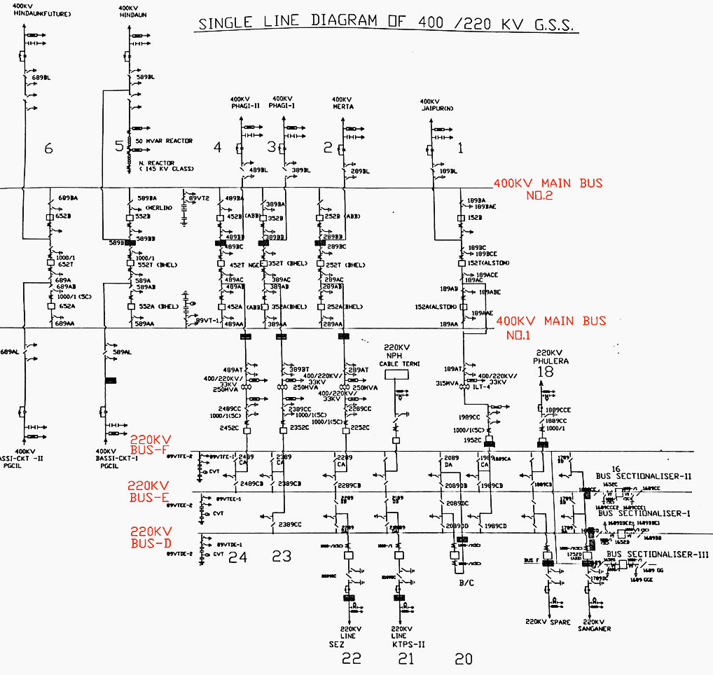
Figure 2 – Single-line diagram of a 400/220 kV substation
2.3. Substation Profile
The profile of substation structures and equipment has become an increasingly important aspect to consider in substation layout. Most substations currently being designed and constructed use low-profile structures and rigid buswork, particularly for low-voltage distribution substations or in areas with natural environmental screening.
Low-profile construction generally uses lower structures with a minimum number of members for support. Larger pieces of equipment, such as power transformers and power circuit breakers, have become smaller over the years.
Generally, the advantages of easier equipment operation and maintenance as a result of reduced equipment sizes and effective locations make up for the expense of purchasing somewhat larger sites.
A comparative display is provided in Figure 3 below.
Related electrical guides & articles


Salem Alshahrani
Electrical engineer (BEE & Meng). Specialized in substation design, especially in LV/MV switchgears and transformers. Passionate in power system planning, analysis, and stability studies.Profile: Salem Alshahrani
