
Estimated Study Time: 20 minutes
HV substation schematics & diagrams
High voltage power substations are complex networks of power and control connections, represented by design elements like- Single Line Diagrams, layout and block diagrams, schematics, logic diagrams, schedules, and so many more. Wiring diagrams and schematics, in a sense, are the blueprints of electrical design.
 Tricks in designing and analyzing schematics and diagrams of high voltage substations
In this article, we aim to familiarize the readers with techniques to design those diagrams and tricks to put them all together to form the core of electrical designs in high voltage power substations. Substation diagrams help ensure that the design norms are followed and serve as a reference for troubleshooting or future extensions.
A case project is used in this article to elucidate the overall design and analytic aspect of substation schematics and diagrams.
- SLD, schematics and wiring diagrams. What’s the difference?
- Breakdown of Single Line Diagrams (SLD)
- Detailing of 132 kV line SLD and protection:
- Busbar protection scheme
- Special mention for transformer differential protection
- Schedules and general arrangement diagrams
- Bonus! Schematics and diagrams (PDF)
1. SLD, Schematics and wiring diagrams
What’s the difference?
An entire substation design package can be overwhelming, even for seasoned and experienced design engineers. The best trick is to lay a principal concept and build on that. Single Line Diagram, for instance, is the best option to play around with the design aspects and grow into the details.
It is basically a conceptual layout of substations, analogous to a physical component layout that helps the designer illustrate the primary components, basic functionalities, and operational flow without getting too much into details of circuits and wiring diagrams.
Schematics shows the function of circuits rather than replicating the physical layout of wires and connections in the real world.
The next part of the substations design drawing is detailed wiring diagrams that illustrate the actual layout of wires and physical connections between devices. Wiring diagrams try to emulate the essence of the actual components by using their abstract version, retaining the details like orientation, pinouts, connection points, etc.
Go back to the Contents Table ↑
1.1 Special addition: Logic diagrams
Logic diagrams are essential parts of the substation drawing package that helps to set up the operation philosophy, which later develops into schematics and wiring diagrams. Multiple tripping and closing functions require a combination or sequence of more than one action, which is where the logic diagrams come in handy.
The main idea is to illustrate the basic logic behind all those operations using common components like AND, OR, and NOR gates.
Suggested Reading – Learn how to analyze wiring diagrams and single line diagram
Learn how to analyze MV switchgear wiring diagrams and single line diagram
Go back to the Contents Table ↑
2. Breakdown of Single Line Diagrams
Being the flag bearer of substation design, SLDs require the most attention and time. In terms of function, it is like combining all the decisions of component selection, placement, and functionality in a single piece of paper. Between leaving out some important pieces of information or making it too crowded with redundant information, there is a thin line of balance.
Primary components and protection system requirements depend on the type of function and operation of the substation. For instance, this switching substation has main and transfer bus bars with differential protection as focal point for all operations.
To illustrate primary components and functionality, a detailed principle Single Line Diagram is sufficient.
Figure 1 – Sample SLD for a high voltage switching substation
The selection of busbar schemes, type and number of power transformers, level of protection, etc. influence how a Single Line Diagram shapes up.
Inclusions in sample SLD:
- Description of incoming and outgoing lines
- Switchgear assembly and surge arrestors with ratings
- Description and illustration of CT cores
- ANSI indications for line protection relays and metering
- Arrangement of busbar with the rating
- Arrangement and rating of Bus PTs
- Switchgear assembly for bus coupling
- Switchgear assembly for outgoing lines
- Description and illustration of CT cores
- Power transformer with ratings and vector group illustration
- ANSI indications for differential protection relays and metering
- Medium voltage switchgear assembly with cable ratings
The control and protection sections are only superficially added in the SLD to indicate functionalities without giving too many details and are often covered by separate detailed schematics.
Suggested Course – The Essentials of Generators, Transformers and Transmission Lines
Power Engineering Course: Generators, Transformers and Transmission Lines
Go back to the Contents Table ↑
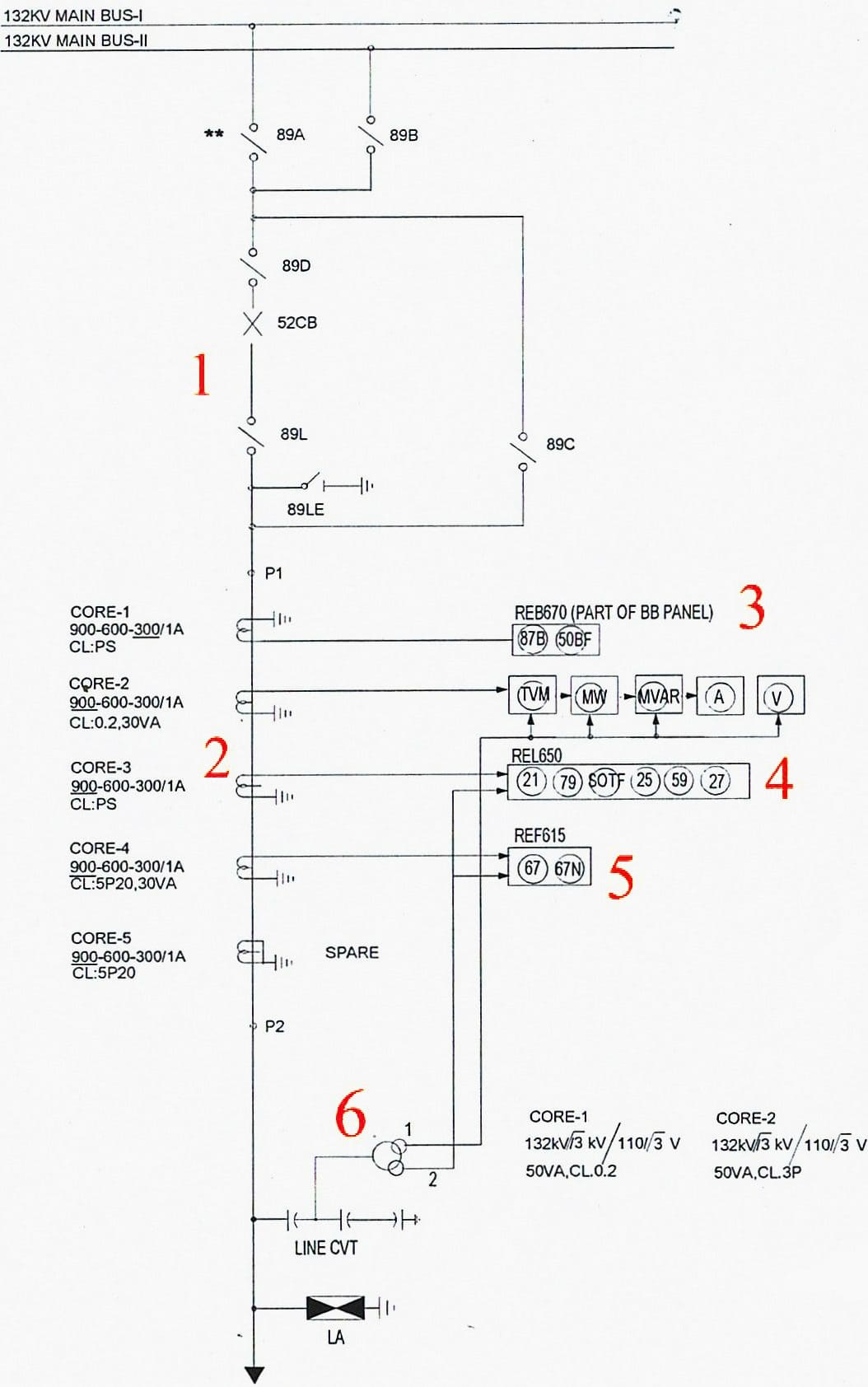
3. Detailing of 132 kV line SLD and protection
Below is a single-line diagram of a 132 kV outgoing line, which is part of the substation illustrated in Figure 1. This section of SLD serves as a base for multiple other sub-systems, schematics, and logic diagrams to form a complete design package of 132 kV line outgoing line protection. The line is protected with a distance protection IED and overcurrent/ earth fault protection back up IED.
The design parts like AC distribution, DC power supply, etc. are common to all sub-sections and thus can be attended as a separate section of the design package.
Figure 2 – SLD of 132 kV outgoing line, elaboration of main SLD
Go back to the Contents Table ↑
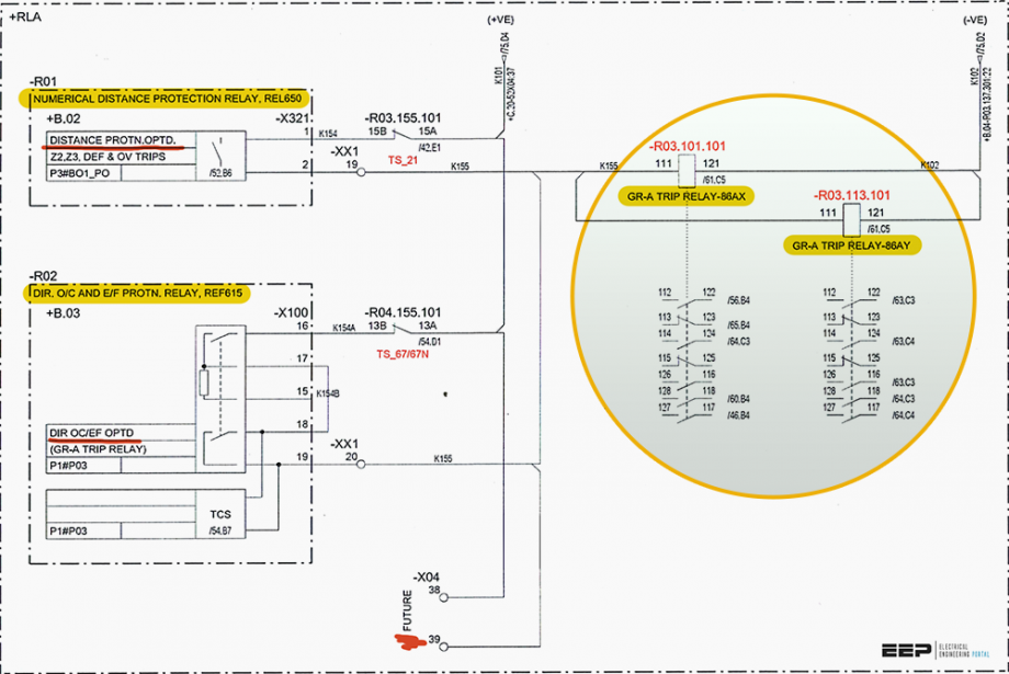
3.1 Switchgear operation schematic
The schematic below is for the operation of isolator switches at the outgoing line bay representing the area marked as “1” in Figure 2. The designer should include the interlocking circuit with an adjacent circuit breaker and isolators to avoid cases of operational hazards.
Provisions of a remote-local selector and interfacing terminals for RTU signals are must-haves for switchyard isolator schematics. The RTU terminal interfaces are important for indication in control panels and SCADA if the substation has one.
Related electrical guides & articles


Bishal Lamichhane
Electrical Engineer (B.E Electrical, M. Sc Engineering) with specialization in energy systems planning. Actively involved in design and supervision of LV/MV substations, power supply augmentations and electrification for utilities and bulk consumers like airports and commercial entities. An enthusiast and scholar of power systems analysis.Profile: Bishal Lamichhane
