


Estimated Study Time: 51 minutes
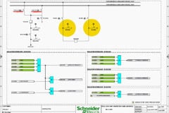
132kV Line-1 Schematics
The execution of a high-voltage circuit breaker trip is the most critical function within any electrical substation. In the provided schematic document for the 132kV Line-1 (=E01) Relay Panel +RP3, the trip circuits are meticulously designed to ensure absolute reliability, speed, and redundancy. The architecture separates the generation of the low-power logical trip signal (the decision-making phase) from the high-power execution of the trip circuit (the physical actuation phase).
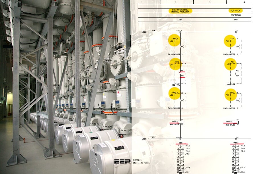 Trip Signal and Trip Circuit Analysis of the 132kV Line-1 (=E01) Schematics (PDF included)
This article provides a microscopic, component-by-component trace of these circuits, explaining the electrical theory, operational mechanics, and precise schematic locations of every element involved in clearing a fault on this 132kV transmission line.
The provided schematic document, “Schematic Drawings 132kV Line-1 (=E01) Relay Panel +RP3.pdf”, serves as the definitive blueprint for the protection and control logic of a 132/11.5 kV Gas Insulated Substation (GIS). Specifically, this document governs the 132kV Line-1, which is designated by the substation system code =E01.
The schematics focus entirely on the internal wiring, logic configuration, and physical apparatus contained within Relay Panel +RP3.
This signal must then be robustly translated, multiplied, and routed through heavily monitored copper pathways (the trip circuits) to actuate the high-power trip coils of the circuit breaker mechanism located in the substation yard.
Here is the download link for the complete PDF document with 132kV Line-1 (=E01) Relay Panel +RP3 schematics (30 pages). Open it up, so you can follow the discussion.
Schematics (PDF, 2.2 MB)
- Part 1: The Generation of Primary and Backup Trip Signals
- Part 2: The Physical Execution of Trip Circuit-1 (TC-1)
- Part 3: The Physical Execution of Trip Circuit-2 (TC-2)
- Part 4: Dynamic Control and Safety Overrides
- Part 5: Conclusion on Trip Circuit Architecture
- Attachment (PDF) 🔗 Design, Supply, Installation, Testing & Commissioning of 230/132 kV & 132/33 kV Substations
Part 1: The Generation of Primary and Backup Trip Signals
Before heavy direct current can be routed to the switchyard to physically pull the breaker contacts apart, the protective relays must make the logical decision to trip. This decision is manifested electrically on Sheet 33, titled “Trip Signals & Trip Circuit Status“.
This section of the schematic serves as the critical bridge between the microprocessor-based intelligence of the relays and the electromechanical actuation of the lockout relays.
1.1 Line Differential / Distance Protection Trip Generation
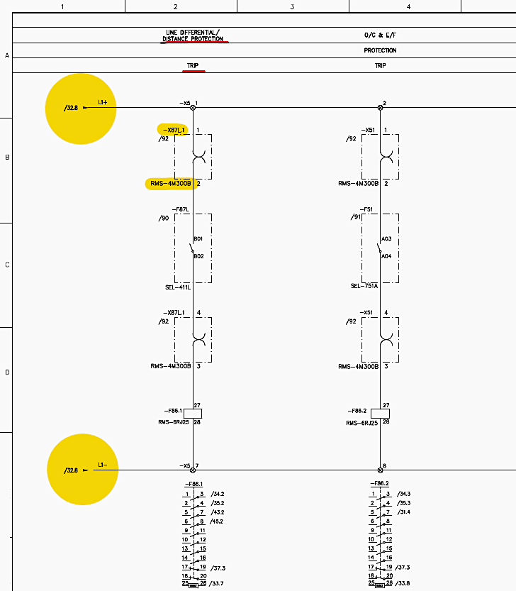
The primary line of defense for the 132kV Line-1 is the Line Differential / Distance Protection relay, designated functionally as -F87L (the SEL-411L relay). The electrical path for generating its primary trip signal is mapped out in explicit detail on Sheet 33, Column 1.
1.1.1 The Source of Actuation Power
Every trip command requires a reliable potential voltage to drive the downstream relays. On Sheet 33, Row B, Column 1, the positive leg of the direct current auxiliary supply, designated as L1+, enters the local circuit.
The schematic specifically notes that this L1+ supply originates from a previous distribution bus, indicated by the cross-reference text “/32.8“. This ensures that the trip generation circuit is drawing from the panel’s secured, breaker-protected DC supply.
Figure 1 – Line Differential / Distance Protection Trip Generation
1.1.2 Routing Through the Primary Relay Test Block (-X87L.1)
Before this positive voltage can reach the protection relay, it must pass through an isolation mechanism. The L1+ wire is routed directly to a relay test block, designated as -X87L.1, which is explicitly identified on the drawing as an RMS-4M300B model.
Input Connection: The live L1+ wire lands securely on terminal number 1 of this test block (Sheet 33, Row B, Column 1).
Operational Theory: The purpose of the -X87L.1 test block is to allow maintenance engineers to safely inject secondary test currents into the -F87L relay without accidentally sending a live trip signal to the switchyard. During normal, undisturbed operations, an internal shorting bar within the RMS-4M300B connects terminal 1 directly to terminal 2.
Output Connection: The L1+ voltage successfully passes through the block and exits via terminal 2, making it available for the relay’s internal logic.
1.1.3 Interfacing with the SEL-411L Protection Relay (-F87L)
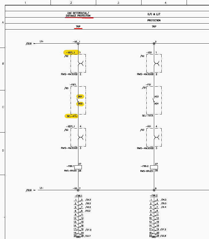
Upon exiting terminal 2 of the -X87L.1 test block, the copper wiring carries the L1+ voltage directly into the SEL-411L Line Differential Protection Relay -F87L.
Relay Entry Point: The voltage enters the relay at a specific hardware input terminal labeled B01 (Sheet 33, Row C, Column 2). Terminal B01 represents one side of an internal, programmable, dry output contact within the IED (Intelligent Electronic Device).
The Logical Tripping Action: Under healthy, non-faulted grid conditions, the microprocessor keeps the internal contact between terminal B01 and terminal B02 strictly open. The L1+ potential rests at B01, unable to proceed.
Upon confirming the fault, the relay issues a high-speed command to close this internal hardware contact.
Relay Exit Point: The physical closure of the contact bridges B01 to B02. The L1+ voltage, now transformed into an active, logic-high “TRIP” signal, surges out of the -F87L relay via terminal B02 (Sheet 33, Row C, Column 2).
Figure 2 – Interfacing with the SEL-411L Protection Relay (-F87L)
1.1.4 The Return Path Through the Test Block
To maintain the integrity of the isolation scheme, the newly minted trip signal must route back through the same test block assembly.
Re-entry: As traced on Sheet 33, Row D, Column 2, the active signal wire is routed from relay terminal B02 back to the -X87L.1 test block, entering at terminal number 3.
Re-exit: It passes through the internal connection of the RMS-4M300B block and exits safely via terminal number 4. If a test plug were inserted by a technician, this path between 3 and 4 would be physically broken, trapping the trip signal safely within the panel and preventing breaker actuation during maintenance.
1.1.5 Energizing the Primary Master Tripping Relay (-F86.1)
The ultimate destination for this generated signal is the primary Master Tripping & Lockout Relay, designated as -F86.1 (Sheet 33, Row D, Column 2).
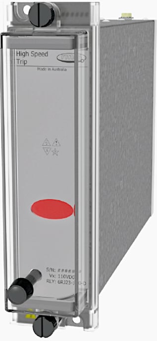
Coil Actuation: The active trip signal travels from terminal 4 of the test block and lands directly on terminal 27 of the -F86.1 relay, which is specified on the schematic as an RMS-6RJ25 model.
Figure 3 – 6RJ25 High Speed Tripping Relay
Circuit Completion: For the -F86.1 internal electromagnetic coil to actuate, it requires a negative return path. As shown on Sheet 33, Row E, Column 1, terminal 28 of the -F86.1 relay is permanently tied to the L1- negative supply bus.
Mechanical Latching: The instantaneous arrival of the L1+ potential at terminal 27, against the permanent L1- potential at terminal 28, creates a powerful electromagnetic field within the 6RJ25 relay. This field forcefully pulls the internal mechanical armature, simultaneously snapping all of the relay’s auxiliary contacts from normally open (NO) to normally closed (NC).
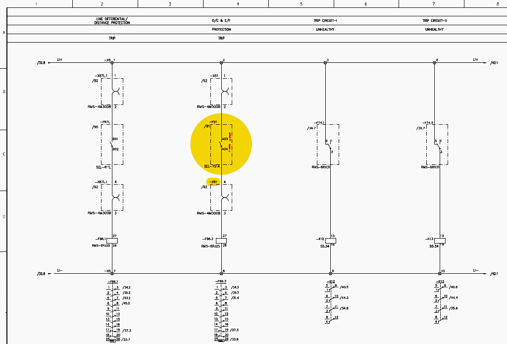
1.2 Over-Current & Earth Fault Protection Trip Generation
Because high-voltage transmission lines are critical to grid stability, a single point of failure is unacceptable. Therefore, a completely parallel and fully independent backup trip generation circuit is deployed.
This secondary logic relies on the Over-Current & Earth Fault Protection relay, designated as -F51 (the SEL-751A relay). The tracing for this backup signal is mapped on Sheet 33, Column 2.
1.2.1 Sourcing and Isolation
L1+ Intake: Just like the primary circuit, the secondary circuit begins with the L1+ positive supply, sourced from the “/32.8” bus (Sheet 33, Row B, Column 2).
Secondary Test Block (-X51): To ensure the backup relay can be tested independently of the primary, the L1+ wire is routed to a completely separate relay test block, designated as -X51. The wire lands on input terminal number 1 of the -X51 test block.
Through the Block: The voltage passes safely through the internal shorting bar of this RMS-4M300B component and exits via terminal 2.
1.2.2 Interfacing with the SEL-751A Protection Relay (-F51)
Relay Entry: After exiting terminal 2 of the -X51 test block, the L1+ voltage is wired into the SEL-751A Over-Current & Earth Fault Protection Relay (-F51). The specific hardware input terminal for this backup trip circuit is labeled A03 (Sheet 33, Row C, Column 2).
The Backup Tripping Action: During standard operations, the internal contact between A03 and A04 within the -F51 relay remains normally open.
Relay Exit: The L1+ voltage, now acting as an active secondary “TRIP” signal, exits the -F51 relay via terminal A04 (Sheet 33, Row C, Column 2).
Figure 4 – Over-Current & Earth Fault Protection Trip Generation
1.2.3 Routing to the Secondary Lockout Relay (-F86.2)
Test Block Return: Following the trace on Sheet 33, Row D, Column 2, this secondary signal is routed back to the -X51 test block, entering at terminal number 3. The signal traverses the internal links and exits safely at output terminal 4.
Coil Actuation: From terminal 4 of the -X51 test block, the backup trip signal is directed to the operating coil of the secondary Master Tripping & Lockout Relay, designated as -F86.2. The wire lands squarely on terminal 27 of this second 6RJ25 relay.
Circuit Completion: Identical to the primary setup, terminal 28 of -F86.2 is permanently connected to the L1- negative supply. The arrival of the positive signal completes the electrical circuit, energizing the coil of -F86.2.
This relay also latches mechanically, permanently memorizing the fault state and cascading the trip command to the secondary actuating systems out in the switchyard.
Part 2: The Physical Execution of Trip Circuit-1 (TC-1)
The successful latching of the master lockout relays -F86.1 and -F86.2 represents the conclusion of the intelligence phase. The system must now route high-amperage direct current out of the protective Relay Panel +RP3, across the physical expanse of the substation switchyard, and directly into the circuit breaker’s mechanical actuating housing. This heavy-duty electrical path is meticulously documented on Sheet 34, titled “Trip Circuit-1”.
This specific circuit is engineered solely to drive Trip Coil 1 (TC-1) within the high-voltage breaker.
2.1 The Primary Lockout Execution Path (via -F86.1)
The most robust method to fire Trip Circuit-1 is via the heavily rated contacts of the primary lockout relay -F86.1, which we previously traced being activated by the SEL-411L relay.
2.1.1 Injecting Power into the Circuit
The L1+ Source: As depicted on Sheet 34, Row B, Column 1, the L1+ positive direct current supply enters this specific schematic sector. Because trip coils require significant current to operate their solenoids, this wiring is typically of a heavier gauge than logic wiring to prevent voltage drop.
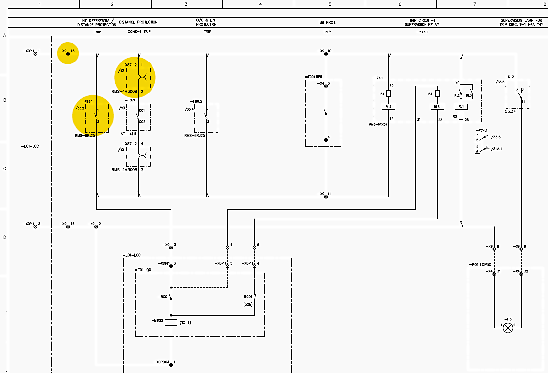
Arriving at the Lockout Contact: The L1+ voltage is immediately routed to a specific set of heavy-duty contacts on the primary Master Tripping & Lockout Relay, -F86.1. The schematic specifically includes a cross-reference notation “/33.2” adjacent to this contact (Sheet 34, Row B, Column 1).
The Execution: The positive L1+ voltage halts at the upper side of this contact. When the fault occurs and the coil of -F86.1 is energized, the mechanical armature slams shut, forcing this specific contact closed.
The solid black line on the diagram illustrates the high-power signal passing through this now-closed gap and exiting the bottom of the contact to continue its path toward the switchyard.
Figure 5 – The Primary Lockout Execution Path (via -F86.1) and Routing to the Field Interface
2.1.2 Routing to the Field Interface
Bypassing Secondary Tests: A crucial design feature visible on Sheet 34, Row B, Column 1 is that the trip path emerging from the -F86.1 lockout relay completely bypasses the local test block (-X87L.2). Once the lockout relay fires, there is no stopping the signal within the panel; it merges directly onto the main outgoing trip bus.
The Main Terminal Block (-X9): The active, high-power trip signal travels to the main interface terminal block array. This array acts as the physical boundary between the controlled environment of Relay Panel +RP3 and the harsh outdoor environment of the switchyard.
As shown on Sheet 34, Row B, Column 2, the signal wire lands securely on terminal block -X9, specifically at terminal number 15.
Related electrical guides & articles




Edvard Csanyi
Hi, I'm an electrical engineer, programmer and founder of EEP - Electrical Engineering Portal. I worked twelve years at Schneider Electric in the position of technical support for low- and medium-voltage projects and the design of busbar trunking systems.I'm highly specialized in the design of LV/MV switchgear and low-voltage, high-power busbar trunking (<6300A) in substations, commercial buildings and industry facilities. I'm also a professional in AutoCAD programming.
Profile: Edvard Csanyi