
Estimated Study Time: 11 minutes
Control and interlocking schemes
Medium voltage switchgear is used for switching medium voltage loads through associated control, measuring, protective and regulating equipment. This operation also involves considerable manual intervention which therefore necessitates the fulfilment of safety requirements laid down in International Standards.
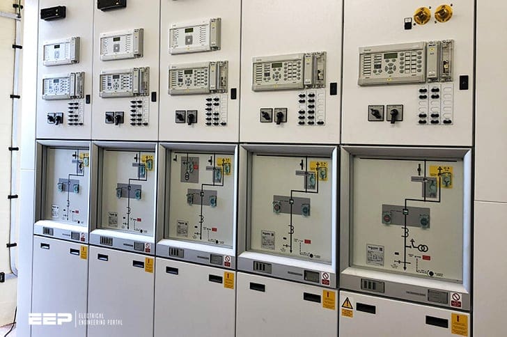 Standard tripping schemes and trip circuit supervision schemes for MV switchgear (on photo:: Medium voltage switchgear type GHA; credit: Bertus de Ruijter - Teamleader Field Services at Schneider Electric)
A variety of control and interlocking schemes are used to achieve the above stated objectives. This technical covers following schemes in detail:
These schemes are the frequently used and are provided in most medium voltage switchgear applications.
1. General – Functional Requirements
A protection relay is usually required to trip a circuit breaker (CB). The power required by the trip coil of the CB may range from 50 W for a small distribution CB to 3000 W for a large EHV CB. Where such appreciable current-carrying capacity is required, interposing contactor type elements will normally be used.
Even though the functional requirements of schemes remain the same, there is always a variation from project to project depending upon the following factors:
- Distribution philosophy of AC, DC supply
- System/bus configuration
- Number of breaker trip coils
- Grouping of alarm signals and trip/non-trip segregation and
- Tripping logic
The above aspects are generally finalized in agreement with the customer and based on experience gained over a period of time.
2. Tripping Schemes
2.1 Shunt Tripping Scheme
This is the most commonly used tripping scheme. The protective relay (PR) contact is arranged directly to trip the circuit breaker and it simultaneously energises an auxiliary unit X which then reinforces the contact that is energising the trip coil. The scheme is shown in Figure 1.
All the above-mentioned tripping schemes envisage the use of separate DC supply for tripping. An alternative scheme using the fault current to trip the circuit breaker is called a series tripping scheme.

2.2 Series Tripping Schemes
These schemes operate by using different components as discussed below.
2.2.1 Using Relays
Here the series trip coil is normally kept shorted through the NC contacts of the series tripping relays. The trip coil comes into the circuit and trips the circuit breaker when the relay contact opens at fault.
The circuit is shown in Figure 2.
2.2.2 Using Summation CT
This scheme is similar to the one using relays but here a summation CT is used to summate the current of all the three phases, thereby minimising the requirement of three series trip coils to one.
The series trip coil is connected to the output of the summation CT and normally shorted through relay NC contacts. The scheme is shown in Figure 3.

2.2.3 Using Motor Protection Circuit Breaker (MPCB)
MPCBs are manual motor starters with thermal and electromagnetic trip features. Normally the trip coil is kept shorted through the MPCB. The MPCB blows off during a fault, and thereby pushing the fault current through the trip coil which, in turn, trips the circuit breaker.
This process is shown in Figure 4 below.
2.2.4 Using Time Limit Fuses
This is similar to the MPCB scheme. Here, in the place of MPCBs, fuses with definite time characteristic are connected across the trip coil.
2.3 Capacitor Tripping Scheme
For installations where DC supply is not available or where it is uneconomical to provide battery / battery charger for DC supply or where the stations are unattended and battery maintenance cannot be guaranteed, a circuit using capacitor banks is employed to provide tripping energy to the breaker trip coil.
In normal service, tripping on faults is done through the diode bridge rectifier’s dc supply. In abnormal conditions of failure of HT PT supply, the tripping energy is derived from energy stored in the charged capacitor banks. Normally the capacitors are rated to store energy for two trip and one close operation.
The scheme is shown in Figure 5.

3. Trip Circuit Supervision Schemes
The trip circuit extends beyond the relay enclosure and passes through more components such as fuses, links, relay contacts, auxiliary switch contacts and so on, and in some cases, through a considerable amount of circuit breaker wiring with intermediate terminal boards. These complications, coupled with the importance of the circuit, have directed attention to the need for its supervision.
The simplest arrangement contains a healthy trip lamp, as shown in Figure 6.

The resistance in series with the lamp prevents the breaker from being tripped by an internal short-circuit caused by failure of the lamp. This provides supervision while the circuit breaker is closed.
In either case, the addition of a normally open push button contact in series with the lamp will make the supervision indication available only when required.

The supervision relay type TCS is intended for a continuous supervision of circuit breaker trip circuit and gives an alarm for loss of auxiliary supply, faults on the trip coil or its wires independent of the breaker position.
Figure 8 illustrates such a scheme, which is applicable wherever a remote signal is required.
Scheme working principle
Under healthy conditions with the circuit breaker closed relays A and C are energized. If the trip circuit opens or the trip supply fails, relay A drops off and opens contact A1 to de-energize relay C. When the circuit breaker is open, relay B is also energized via the normally closed auxiliary switch of the circuit breaker and relay C is held in by contact B1.
Relay B will detect trip circuit abnormalities with the circuit breaker open in a similar manner as relay A with the circuit breaker closed.
Relay C is time delayed on drop-off by means of an RC circuit for a total time of 350 to 800 milli-seconds, to prevent a false alarm due to voltage dips caused by faults in other circuits or during a normal tripping operation, when relay A is momentarily short-circuited by the self re-set tripping relay contact.
If the trip relay fails to re-set, possibly due to the failure of the circuit breaker tripping mechanism, the alarm is initiated.
The alarm supply should be independent of the tripping supply so that an indication will be obtained in the event of the failure of the tripping battery.
3.1 Trip circuit supervision scheme (VIDEO)
In a protection system the tripping of circuit breaker is crucial. Should an interruption occur in trip circuit, possible network fault would not be disconnected and the fault would have to be cleared by another upstream protections in the power system.
The supervision relay type TCS is intended for a continuous supervision of circuit breaker trip circuit and gives an alarm for loss of auxiliary supply, faults on the trip coil or its wires independent of the breaker position.
References //
- Switchgears book by BHEL – Bharat Heavy Electricals Limited
- Trip circuit supervision relay TCS Product Guide by ABB
Related electrical guides & articles


Edvard Csanyi
Hi, I'm an electrical engineer, programmer and founder of EEP - Electrical Engineering Portal. I worked twelve years at Schneider Electric in the position of technical support for low- and medium-voltage projects and the design of busbar trunking systems.I'm highly specialized in the design of LV/MV switchgear and low-voltage, high-power busbar trunking (<6300A) in substations, commercial buildings and industry facilities. I'm also a professional in AutoCAD programming.
Profile: Edvard Csanyi

Trip Circuit Supervision in schemes using 86 or 94 to trip the circuit breakers is more complicated, because in these schemes the digital relays do not trip the circuit breaker directly but through an intermediate relay (either 94 or 86)
Excelente resumen. Para recomendar
Wow how am fully happy in how the explanation is being explain into step by step procedure.🤑🤑🤫🤫🖐️🖐️ yeah
Trip Circuit Supervision 27T and 98T if all 3 phase trip coils are healthy TDDO is energized and symbol used is for Time Delay On timer but it is Time Delay Off timer. More over if common DC is lost for all panels trip circuit faulty alarm appears in all panels. It is better to block alarm with NO contact of DC supply supervision relay K12 of Siemens. Moreover 52b contact used in series with 98T is not needed and trip coil may be connected direct to 98. I have 52 years hands on experience in testing and commissioning ABB/Sweden 9840229620
Hi dear, I hope you be fine , I would like to informed you we will be glad to cooperate oil and gas company with us also we have many project and request to send so let us know if you could cooperate and original with us.Let me know your conclusion and I hope you could help us in our project and be our best supplier .Please send us your commercial and technical offers according to the details that is mentioned in the below table . In advanced thanks for your cooperation and I’m looking forward to hear from you. For any information don’t hesitate to contact us.
Our requested product is:
PARTS FOR POWER STATIONBest Regards
Nadia
Excellent explanation
Dear anyone,
which size of cable and which type of cable is suitable for 1200 meter length,400V distribution line.
The Explanation is OK. Not so-good.
Very nice presentation
Very good approach
Edvard,
Good article; one slight glitch: fig. 6 is identical with fig. 7, but they describe different situations. Fig. 6 was presumably not intended to have the n/c auxiliary contact (52b).
I would like to say the same thing, FIG.6 should only contain 52a contact, which is normally open contact and when CB is in closed position, TC will be supervised through this auxilary contact.