
General Troubleshooting Procedure
The Symptom – The machine does not start when the start button is pressed. At this point the problem could be mechanical or electrical. We will focus on just the electrical circuit faults for now. This fault could be located in either the power circuit or the control circuit. The fault could also be many different types, such as, open circuit fault, short circuit fault or a ground fault.
 Troubleshooting An Open Circuit Faults in the Control Circuit (photo credit: lpmanagementservices.com)
This general troubleshooting procedure is designed to start in the middle of the problem area and give us the best idea which direction to go. The control transformer is a good place to start since it is in the middle of the circuit and is part of the power and control circuits.
The first three steps of this procedure will be the same for all faults and the rest will be completed throughout this chapter in more than one procedure. There is no one procedure that can guide you through any given problem. For simplicity’s sake we will now take one area and one type of fault at a time. The first fault we will investigate is the open circuit fault.
We will now investigate open circuit faults in the control circuit.
Open Circuit Faults in the Control Circuit
Open circuit faults – An open circuit fault is any fault that stops the operation of a machine due to an open wire or component. Let’s develop our procedure for troubleshooting an open circuit in the control circuit. Remember that the first three steps will be the same for all faults.
Step 1
You must analyze the schematic diagram for a general circuit overview.
Step 2
You must carefully open the control panel with power energized since voltage checks will need to be made. (The operation of the voltmeter should have been verified before continuing)
Step 3
You should check the voltage at the X1 and X2 terminals at the secondary of the control transformer.
- If correct voltage is not present, then the problem is in the power circuit.
- If correct voltage is present and the contactor is energized, then the problem is in the power circuit.
- If correct voltage is present, the contactor is not energized and the OL is not tripped, then the problem is in the control circuit.

Scenario – What’s happening?
Scenario is the motor does not start when the start button is pressed. The correct voltage is present at X1 and X2, the contactor is not energized and the OL is not tripped, then the problem is in the control circuit. For this scenario, the fault is an open circuit fault and inside the panel. From the schematic on the previous page you should have read 120 volts at terminals X1 and X2.
Since the correct voltage is present we must troubleshoot the system in a logical order until we lose the correct voltage.
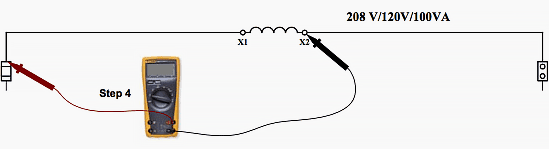
Step 4 //
You should check the voltage on X1 at the top of the control circuit fuse and X2 terminal at the secondary of the control transformer.
- If the correct voltage is present, continue to Step 5.
- If the correct voltage is not present, then X1 wire is open from the top of the fuse to the terminal on the secondary of the transformer.
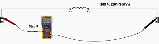
Step 5
You should check the voltage on X1 at the top of the control circuit fuse and X2 at the top of the neutral link.
- If the correct voltage is present, continue to Step 6.
- If the correct voltage is not present, then X2 wire is open from the top of the neutral link to the terminal on the secondary of the transformer.
Step 6
You should check the voltage on wire #1 at the bottom of the control fuse and X2 at the top of the neutral link.
- If the correct voltage is present, continue to Step 7.
- If the correct voltage is not present, then the control fuse is open.If the fuse is open, then there is either a short circuit or ground fault. If the fuse is not open, then there is an open circuit fault. This is our first indication that the fault is an open circuit fault.

Step 7
You should check the voltage on wire #1 at the bottom of the control fuse and wire #2 on the bottom of the neutral link.
- If the correct voltage is present, continue to Step 8.
- If the correct voltage is not present, then the neutral link is open.

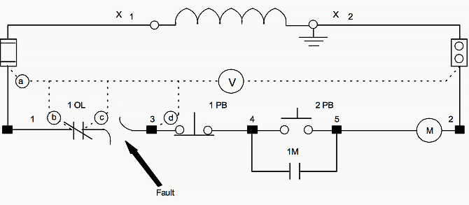
Use the schematic diagram below as an illustration for Scenario A, assuming that we don’t know the location of the fault:
Step 8
Since the voltage at point a (bottom of the fuse) is the correct voltage, we will use wire #2 as our reference. We will make our measurements from left to right and then top to bottom until we find the voltage not present. If the correct voltage is present, continue to Step 9.
Step 9
Check the voltage at point b (left side of 1OL) with wire #2 as a reference. If the correct voltage is present, continue to Step 10.
- If the correct voltage is not present, then wire #1 is open from the bottom of the fuse to the left of the normally closed contacts for 1OL.
Step 10
Check the voltage at point c (right side of 1OL) with wire #2 as a reference.
- If the correct voltage is present, continue to Step 11.
- If the correct voltage is not present, then 1OL normally closed contacts are open.
Step 11 //
Check the voltage at point d (top of terminal #3) with wire #2 as a reference.
- If the correct voltage is present, continue to Step 12.
- If the correct voltage is not present, then wire #3 is open between the right side of 1OL and the top of #3 terminal.
Reference // Electrical Theory – Technology, PLC Concepts and Basic Electronics – Michelin North America, Inc. (Download)


Great work may GOD bless you
Not true and too simplified. A high resistance fault could be the cause and I’ve seen in real life.
When I press start button the motor start,when the motor reaches the maximum speed the soft starter trip with bypass open Error 71 but when start the motor by using DOL the motor runs with no problem
I’m looking for attachment plz for electrical engineering
Can you provide me an open fault calculation or what is difference for the open circuit fault, ty
Article 430.74 of the National Electrical Code states,” Where one conductor of the motor control circuit is grounded, the motor control circuit shall be arranged so that a ground fault in the control circuit remote from the motor controller will (1) not start the motor and (2) not bypass manually operated shutdown devices or automatic safety shutdown devices.Therefore the drawing for a start/stop control circuit is a clear violation of the National Electrical Code. Also the overload device is is located after the magnetic coil and not before the start push button.
You’re not looking at the circuit correctly Gilbert. A ground fault anywhere on the ungrounded side of the coil will not start the motor, it will open the fuse instead since X2 is grounded.
The OL contact may be located anywhere in the ungrounded side of the control circuit if you desire. The NEC does not prohibit you from changing its location in the circuit. When you take a new motor starter out of the box the manufacturer typically pre-wires the OL contact so that you do not have to. Whether or not the OL contact breaks the grounded side of the circuit depends on other factors. For instance if it was a 480 V control circuit it would open the other ungrounded leg of the control circuit.
Yes it does. The OL contact on the motor starter was tested at a nationally recognized testing laboratory such as the UL with the connection to it designated X2 for a reason, not my convenience. NEC 110.3(B) states Listed or labeled equipment shall be installed and used in accordance with any instructions included in the listing or labeling. The circuit illustrated clearly has a control transformer.