


Estimated Study Time: 61 minutes
Field Diagnostics Approach
To be honest, troubleshooting low-voltage Power Factor Correction (PFC) banks on-site is not an exercise in academic theory; it is a highly physical, hazardous, and systematic process. When a facility manager reports a penalty on their utility bill, or a breaker trips seemingly at random, the technician standing in front of the metal enclosure needs actionable steps, not complex mathematical derivations.
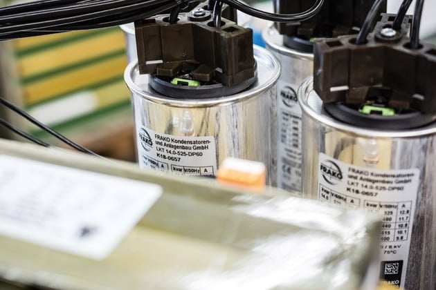
 Troubleshooting LV Reactive Power Compensation On-Site (photo credit: Frako)
This guidance article is designed specifically for field engineers and technicians. It strips away the abstract physics and focuses entirely on what you can see, hear, smell, and measure with standard industrial diagnostic tools.
The practical approach to PFC troubleshooting demands a specific sequence of operations. You must never immediately start replacing parts based on a hunch.
Throughout this technical article, I will focus heavily on tool usage. Your primary weapons are a CAT IV True-RMS (TRMS) clamp multimeter, a thermal imaging camera, a dedicated LCR (Inductance, Capacitance, Resistance) meter, and a phase rotation meter.
I will detail exactly where to place your probes, what dials to turn, and how to interpret the numbers on the screen. A reading of 30 Amps means nothing unless you know the practical formula to determine if it should actually be 45 Amps.
This guide provides those exact field parameters.
- Immediate Safety & LOTO Execution:
- Controller Diagnostics – What the Screen Means:
- Current Transformer (CT) Field Troubleshooting:
- Capacitor Field Measurements and Diagnostics:
- Contactor and Switchgear Diagnostics:
- Harmonics and Reactor Troubleshooting:
- Environmental & Physical Diagnostics:
- Modern Grid Troubleshooting (Solar & Unbalance):
- Establishing a Diagnostic Maintenance Routine:
- Final Troubleshooting Notes
- Attachment (PDF) 🔗 Download Study ‘Impact of Restricted Earth Fault Relays on Protection Stability in Shunt Capacitor Banks’
1. Immediate Safety & LOTO Execution
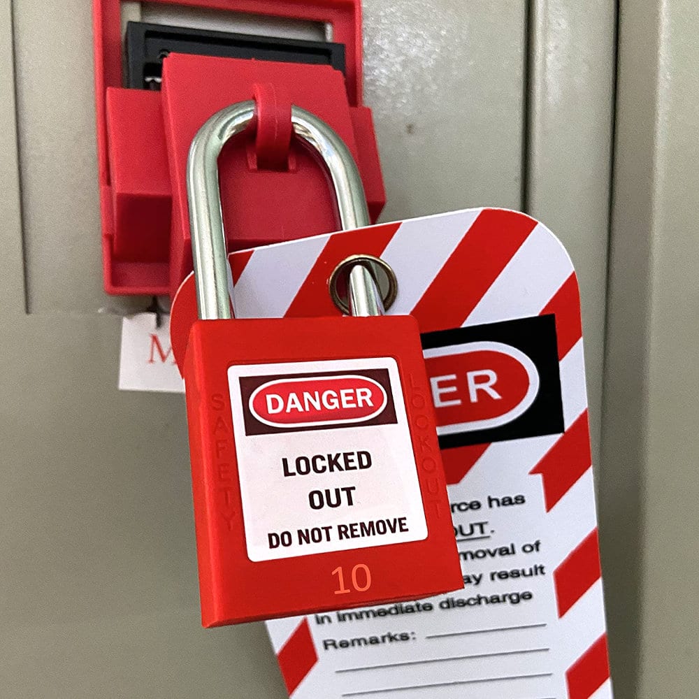
A reactive power compensation panel is fundamentally a energy storage bomb. Unlike motor control centers where power stops when the breaker is thrown, a PFC panel remains highly lethal after disconnection. The first practical step in any troubleshooting scenario is implementing a strict Lockout/Tagout (LOTO) procedure.
Do not rely on the local rotary switch on the panel door! You must trace the feed back to the main distribution board and lock it out at the source. This prevents someone else in the facility from resetting what they assume is a nuisance trip while your hands are inside the cabinet.
After five minutes, gear up. Put on a HV face shield and Class 0 (1000V) dielectric gloves with leather protectors. Open the panel doors slowly, standing off to the hinge side rather than directly in front of the opening. This physical positioning ensures that if an arc flash or capacitor rupture occurs as the door opens, the blast wave and debris are directed past you, rather than directly into your chest and face.
Always treat an unverified panel as live.
Figure 1 – Close-up of a main panel disconnect handle secured with a red LOTO padlock and danger tag
1.1 Handling Failed Discharge Resistors on Site
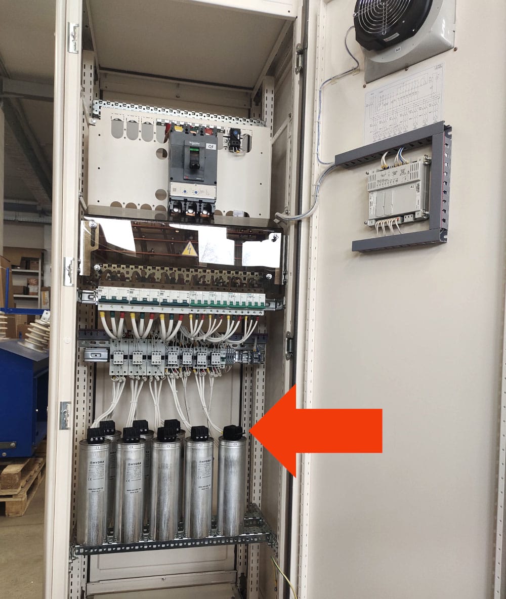
When you approach a PFC panel to test capacitors, you must practically verify that the internal discharge resistors have not failed. With your Class 0 gloves on, take your TRMS multimeter and set it to read DC Voltage, not AC voltage. When a capacitor is disconnected from the AC grid, it traps the charge at the exact moment of the sine wave when the contactor opened.
This leaves a pure DC voltage, which can be up to 560V DC on a standard 400V system. Place your probes directly across the L1 and L2 terminals of the first capacitor can.
It’s extremely important to note that you must use a purpose-built, heavily insulated short-circuiting wand with a high-wattage damping resistor built into the handle.
Hold the wand by the insulated grip. firmly touch the probes across L1 and L2, then L2 and L3, and finally L1 and L3. You will likely hear a loud ‘crack’ and see a bright blue spark upon the first contact. Do not flinch and pull away; hold the connection solid for at least five seconds to drain the core.
Finally, short all three phase terminals directly to the panel’s ground busbar to eliminate any floating residual charge. Only after this physical shorting is complete for every single capacitor in the bank can you safely remove your gloves for detailed component inspection.
Figure 2 – Terminals of discharge resistors on top of capacitor banks
1.2 Arc Flash PPE and Safe Approach Protocols
PFC banks are almost always installed immediately downstream of the main incoming utility transformer to minimize reactive currents flowing through the main switchboard. In practical terms, this means the short-circuit fault current at the PFC busbars is immense, frequently exceeding 50kA.
If a fault occurs while you are troubleshooting, the resulting arc flash will reach temperatures hotter than the surface of the sun. Approaching these panels in a standard cotton uniform is a fatal mistake.
If you are taking live amp readings with a clamp meter, you must also wear voltage-rated gloves with leather protectors, because you will be physically reaching your hands near live, uninsulated busbars.
Before putting a tool into the panel, perform a visual safety sweep. Look for loose wires dangling near the main busbars, signs of water ingress, or heavy layers of black, conductive soot on the insulators. If you see deep black scoring marks on the metal dividers or smell the sharp, acrid odor of ozone (which indicates active electrical arcing), do not attempt live diagnostics.
Immediately execute a complete LOTO at the main breaker, wait out the discharge time, and proceed with entirely de-energized visual inspections.
No live reading is worth an arc flash blast.
Figure 3 – Maintenance crew wearing Category 2 Arc Flash Personal Protective Equipment (PPE)

2. Controller Diagnostics – What the Screen Means
The automated power factor controller mounted on the front door is your primary diagnostic interface. Before you ever open the cabinet or pick up a screwdriver, you must interrogate this device. It tells you exactly what the system thinks is happening. The most common troubleshooting mistake is assuming the controller is broken when it acts erratically.
In 95% of cases, the controller is functioning perfectly, but it is receiving garbage data from the network or has been programmed incorrectly by the previous technician.
Next, check the phase angle or the Power Factor sign. If the factory has large motors running, the system should be inductive (usually indicated by a lagging sign, an ‘L’, or a positive kVAr reading depending on the brand). If the controller says the system is highly capacitive (leading, ‘C’, or negative kVAr) while no capacitors are switched on, you immediately know you have a wiring error.
The controller’s voltage reference inputs and the CT input are crossed, causing a 120-degree or 180-degree phase shift in its internal math. The controller is fine; the wiring is wrong.
Watch Video – Navigating PFC controller screens
2.1 Fixing the “Hunting” (Rapid Switching) Phenomenon
One of the most destructive scenarios you will encounter in the field is “hunting.” You will walk up to the panel and hear a continuous, rapid-fire clicking: CLACK-clack, CLACK-clack. The controller is slamming capacitor steps in, immediately pulling them out, and repeating the process every few seconds.
This will violently destroy the contactors and boil the capacitors within days. You must stop this immediately by switching the controller to ‘Manual’ mode or cutting the control power.
If the delay is correct, the issue is the C/k ratio (the sensitivity threshold). If the facility’s load is fluctuating rapidly (e.g., welding machines or cranes), and the smallest capacitor step in the bank is too large (e.g., 50 kVAr), the controller will switch it on, overshoot the target, immediately switch it off, undershoot, and repeat. You must enter the menu and decrease the sensitivity. Increase the C/k threshold manually so the controller ignores small load fluctuations.
If the load requires fine tuning, the only physical solution is to install a smaller capacitor step (e.g., 12.5 kVAr) for step 1, and reprogram the controller sequence to utilize it.
Watch Video – Contactor chatter (credit: @restaurantrepairs)
2.2 Resolving “Export Power” Errors
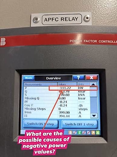
A frequent callout involves a PFC panel that has completely locked itself out and is displaying an “Export” error, or showing negative kW. The customer will tell you, “We don’t have solar panels, we aren’t exporting anything, the panel is broken.” In this scenario, the panel is doing exactly what it was built to do. It measures the vector relationship between the voltage and the current.
If that vector is shifted by exactly 180 degrees, the math indicates power is flowing backward into the grid.
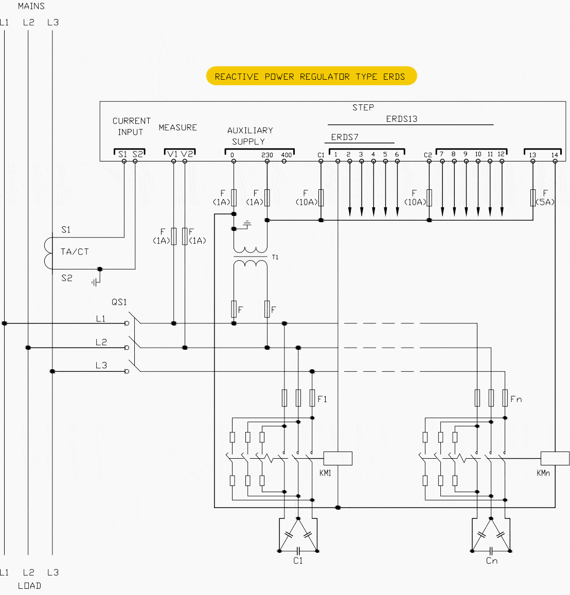
To fix this practically, you do not need to shut down the whole factory to flip the CT mechanically. Open the PFC control panel and locate the terminal block where the two wires from the CT (usually marked S1/k and S2/l) enter the controller. Put the controller in manual mode, turn off all steps.
Simply swap the S1 and S2 wires in the terminal block. This reverses the polarity digitally. Turn the controller back to auto; the kW reading will immediately turn positive, and the system will begin compensating correctly.
Figure 4 – Negative power displayed on Power Factor Controller
2.3 Manual C/k Ratio Configuration
Many modern controllers have an “Auto-Setup” feature that attempts to map the step sizes and calculate the C/k ratio automatically. In environments with high harmonic distortion or rapidly shifting loads, this auto-setup will fail repeatedly, causing the controller to display an error and refuse to operate.
You must know how to bypass the automation and program the controller manually.
I = 25,000 / (1.732 × 400) = 36.08 Amps. This is the primary current the step will pull.
Now, determine what that current looks like on the secondary side of the CT, which is what the controller actually sees. The CT ratio is 1000 to 5, which simplifies to 200 to 1. Divide the step current by the ratio: 36.08 / 200 = 0.18 Amps. The C/k value you must manually enter into the controller is 0.18. Enter the setup menu, turn off ‘Auto-Setup’, navigate to the C/k parameter, input 0.18, and save.
The controller will now have a precise mathematical baseline and will immediately start switching correctly.
Watch Video – Power Factor Regulator: Manual C/K Setting
3. Current Transformer (CT) Field Troubleshooting
The Current Transformer (CT) is the eyes of the PFC system. If it is blind, or looking at the wrong thing, the entire compensation bank is useless. One of the most persistent and hard-to-diagnose problems in the field is incorrect physical placement of the CT.
The golden rule is: The CT must measure the total facility load AND the capacitor bank’s current!
It must be installed on the main incoming feed, upstream of the point where the PFC panel taps into the busbar.
Conversely, if the CT is installed on the wire feeding the PFC panel itself, it only measures pure capacitive current. The controller will read an incredibly low leading power factor, get confused, and shut down completely. It will never switch on a single step. Troubleshooting CT placement requires physically tracing the thick copper busbars inside the main switchroom.
You must visually confirm that the main utility cables pass through the CT donut before any branch circuits or PFC feeds break away from the bus.
Figure 5 – Power Factor Regulator’s Wiring Diagram
3.1 Load Testing to Verify CT Placement
Sometimes, in older industrial facilities, tracing the busbars visually is impossible because they are hidden behind steel plating or routed through concrete floors. You must perform a dynamic load test to prove the CT is in the correct location. You will need a TRMS clamp meter and a radio to communicate with the facility manager or machine operator.
First, go to the PFC controller, put it in Manual mode, and switch off all capacitor steps. Read the total Amperage (I) displayed on the controller screen. Write it down. Next, have the facility manager turn on a large, known load, for example, a large 100kW chiller compressor or a ventilation fan. Watch the controller screen. The amperage should jump up immediately.
If the amperage did jump, you must now test the capacitor loop. With the large load still running, manually engage the largest capacitor step via the controller’s manual menu (e.g., turn on a 50 kVAr step). Watch the current and the Power Factor reading. The Power Factor should immediately improve (move closer to 1.00), and the total apparent current should slightly decrease. If the controller clicks the contactor in, but the screen’s readings do not change by even a fraction, the CT is downstream of the PFC tap.
It cannot see the capacitors. The CT must be physically moved closer to the utility transformer.
Further Study – Installing and setting into operation of automatically controlled compensation banks
Installing and setting into operation of automatically controlled compensation banks
3.2 Safely Reversing CT Polarity on a Live Busbar
If you have verified that the CT is installed backward (P2 facing the source instead of P1), and swapping the secondary wires at the controller terminal is not an option (perhaps due to utility metering rules or shared instrumentation), you may need to physically flip the CT.
If it is a solid-core CT on a main 2000 Amp busbar, you cannot simply unbolt the live bus. If you have a split-core CT, you can open it and flip it, but doing this while the main bus is live requires extreme caution to avoid the lethal open-secondary voltage hazard.
A Current Transformer functions as a step-up voltage transformer if the secondary loop is opened while primary current is flowing. If you simply disconnect the S1 and S2 wires while the factory is running, the voltage across those two small wires will instantly spike to thousands of volts, destroying the CT insulation and potentially causing a lethal shock or arc flash in your hands.
You must never open the secondary circuit of a live CT.
Once the CT is successfully shorted at the block, you can safely disconnect the wires heading to the controller, open the split-core CT, flip it around on the busbar, reconnect the wires, and finally, carefully remove the shorting link to restore the signal to the controller.
Testing Guide (PDF) – Beginner’s Guide to Electrical Testing of Power Transformers
Beginner’s Guide to Electrical Testing of Power Transformers
4. Capacitor Field Measurements & Diagnostics
Capacitors do not last forever. They are consumable items that slowly lose their capacity over years of operation due to a process called self-healing. Every time a micro-surge hits the grid, a tiny portion of the capacitor’s internal metallic film vaporizes to isolate the fault. Over time, a 50 kVAr capacitor might degrade into a 25 kVAr capacitor.
The panel will look perfectly fine, the lights are on, the contactors pull in, but the utility bill will show a penalty because the reactive power output has plummeted. Diagnosing this requires active field measurement.
The most practical way to test a running panel is using a True-RMS (TRMS) clamp meter. You must use a TRMS meter. A cheap, average-responding meter will read the harmonic-rich current of a capacitor bank incorrectly, often displaying values 20% to 40% lower than reality, leading you to falsely condemn perfectly healthy capacitors.
A common mistake is measuring only L1 and assuming the others are fine. Three-phase capacitors frequently fail on just one internal leg. If L1 reads 45A, L2 reads 45A, but L3 reads 22A, that capacitor module has partially failed internally and must be completely replaced. It cannot be repaired.
Watch Video – How to check capacitor bank panel
4.1 Calculating Expected Current vs. TRMS Current
Once you have measured the TRMS current on all three phases, you need to know if that number is good or bad. You cannot simply look at the sticker on the capacitor. A capacitor sticker might say “50 kVAr / 400V / 72A“. If you measure 66 Amps in the field, your first instinct might be that the capacitor has degraded by 10% and needs replacing.
This is a very common troubleshooting error. Capacitor output is heavily dependent on the actual grid voltage in the facility.
Use the standard formula:
Expected Amps = (Rated kVAr × 1000) / (1.732 × Rated Voltage). For the 50 kVAr unit at 400V, that’s 72.1A.
Now, adjust for the real voltage: Actual Amps = Expected Amps × (Actual Voltage / Rated Voltage). So, 72.1A × (385V / 400V) = 69.4 Amps.
Therefore, at 385V, a perfect, brand new 50 kVAr capacitor will draw 69.4 Amps. If you measured 66 Amps, the capacitor has only degraded by about 5% (66/69.4 = 0.95), which is well within acceptable operational limits. Do not replace it. Always do the math based on actual site voltage.
Good Reading – Inside the capacitor bank panel: Power factor correction, calculation and schematics
Inside the capacitor bank panel: Power factor correction, calculation and schematics
4.2 Using an LCR Meter on a De-energized Bank
While live TRMS current measurement is excellent for quick diagnostics, the most accurate way to verify capacitor health is to measure its exact capacitance using an LCR (Inductance, Capacitance, Resistance) meter during a scheduled shutdown. This eliminates all variables like fluctuating grid voltage or harmonic distortion.
This test must be done completely de-energized, following strict LOTO and manual discharge procedures as outlined in Topic 2.
Look at the manufacturer’s nameplate on the side of the capacitor. It will state the nominal capacitance, for example, “3 x 165 µF“. Compare your meter readings to this nameplate. A standard industry rule of thumb is that if the measured capacitance drops more than 10% below the nameplate value (e.g., if it reads below 148 µF), the capacitor has reached the end of its reliable lifespan.
Even if it is still partially functioning, it should be marked for replacement during the current shutdown to prevent rapid acceleration of failure when energized.
Figure 6 – Technician using an LCR Meter on a De-energized Capacitor Bank

4.3 Visual Signs: Bulging and Ruptures
Not all capacitor failures require a meter to diagnose. Cylindrical LV capacitors have a mechanical safety mechanism built into their design. When a capacitor overheats or suffers severe internal shorting, the dielectric gel begins to boil, producing gas. To prevent the aluminum can from exploding violently, the lid is designed to expand upwards.
As the lid pushes up, it physically snaps a set of internal breakaway wires, safely disconnecting the capacitor from the live circuit.
When you open a PFC cabinet for visual inspection, take a flashlight and shine it horizontally across the tops of the capacitor array. Look for uniformity. If one or two cans look noticeably taller than the rest, or if the metal lid containing the terminals is domed upwards like a bloated tin can, those capacitors have failed completely. Their internal safety disconnects have fired. They are dead and must be replaced.
The moment the panel is re-energized, that capacitor will instantly rupture, shooting boiling dielectric fluid and shrapnel throughout the switchboard, initiating a phase-to-phase arc fault. If it bulges, do not touch it; replace it.
Watch Video – APFC Panel Blast and Burning
5. Contactor and Switchgear Diagnostics
The contactors in a PFC bank work harder than almost any other switchgear in a facility. They are slamming closed against inrush currents multiple times an hour. Therefore, standard motor contactors cannot be used. PFC banks use specialized capacitor contactors equipped with a pre-charge block mounted on top. This block contains thin resistive wires and leading auxiliary contacts.
When the coil energizes, these leading contacts close a few milliseconds before the main contacts, forcing the initial surge of current through the resistive wires to damp the inrush.
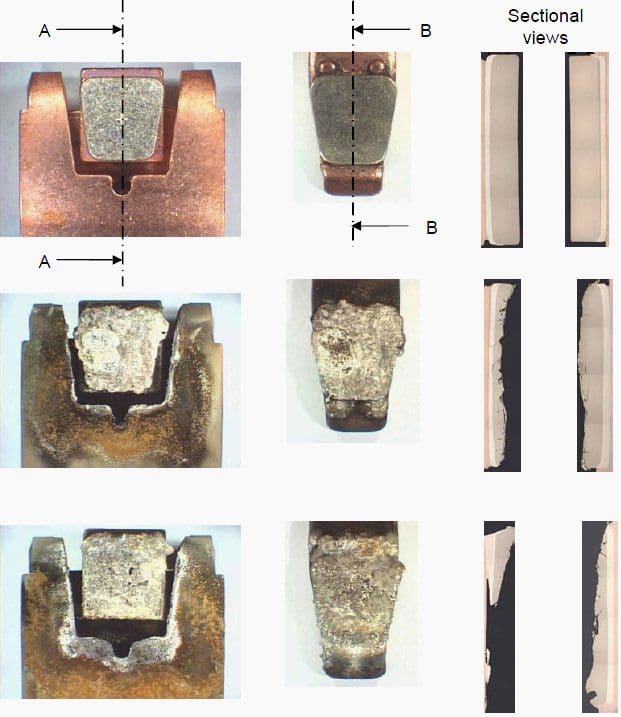
A contactor with broken pre-charge wires is a ticking time bomb. Even if the main contacts are currently pulling in and dropping out correctly, they will inevitably weld together in the near future.
You cannot replace just the resistor wire. You must replace the entire top auxiliary block, or ideally, the entire contactor unit, as the main contacts have likely already suffered severe pitting from operating without the pre-charge protection.
Figure 7 – Inspecting top-mounted pre-charge resistors
5.1 Identifying Welded Main Contacts
When the main contacts of a contactor melt and weld themselves together, the system enters a highly dangerous state. The automated controller will turn off the control voltage to the contactor coil, assuming the step is disconnected. However, because the contacts are physically fused, the capacitor remains hard-wired to the grid. This leads to continuous over-compensation, high grid voltages during light load periods, and severe utility penalties.
To diagnose a welded contactor on-site, you need a TRMS clamp meter and access to the controller interface. Put the controller in Manual mode. Manually command every single step to the “OFF” position. Ensure the controller screen indicates that all steps are disengaged. Now, gear up with your arc flash PPE and open the panel door.
To confirm this electrically, take your TRMS clamp meter and check the thick wires leading from the suspect contactor down to the capacitor. Even though the controller says the step is off, your meter will show full operating current (e.g., 65 Amps) flowing through the wires. You must immediately shut down the main panel breaker, execute LOTO, and replace the welded contactor.
Never attempt to pry the welded contacts apart with a screwdriver to “save” the part. The silver plating is destroyed, and it will simply weld again on the very next cycle.
Figure 8 – Contacts of a power contactor at various stages of the life span with AC-3 loading
5.2 Thermal Imaging for Loose Connections
The constant 50/60Hz electromagnetic vibration of the components, combined with the thermal expansion and contraction from continuous switching, guarantees that bolted connections will loosen over time. A loose connection on a high-current busbar creates localized electrical resistance. This resistance generates intense heat, which oxidizes the copper, creating even more resistance in a runaway thermal cascade that ends in a panel fire.
Relying on visual discoloration to spot this is a mistake; by the time copper turns black, the plastic housing is already melting. So, be wise.
You are looking for thermal anomalies, specifically, temperature differences between phases. If L1 and L3 on a contactor are reading 45°C, but L2 is glowing bright red on your screen at 95°C, you have found a loose or corroded connection. Record the exact location. Do not attempt to tighten the bolt while live.
Complete your thermal sweep, shut down the main feed, apply LOTO, wait the discharge period, and then use a calibrated torque wrench to disassemble, clean, and properly re-torque the overheating connection.
Figure 9 – Technician finding loose connections using an infrared thermal imaging camera

6. Harmonics & Reactor Troubleshooting
In modern industrial facilities dominated by Variable Frequency Drives (VFDs) and LED lighting, the electrical current is no longer a nice sine wave. It is jagged and full of high-frequency noise called harmonics. Capacitors naturally act as a vacuum for these high frequencies. If standard capacitors are installed in a factory full of VFDs, they will suck in amounts of harmonic current, overheat, and explode.
To prevent this, heavy iron-core inductors (called detuning reactors) are wired in series with the capacitors to choke out the harmonics.
Troubleshooting detuned PFC panels requires different techniques. Reactors get incredibly hot under normal operation. A standard reactor operating safely can easily reach surface temperatures of 90°C to 110°C. If you use a thermal camera and see a reactor at 100°C, do not panic; this is often within its design parameters (which usually allow for 115°C rises above ambient).
A practical field test for reactor health is listening. A healthy detuned reactor hums with a steady, low-frequency vibration. If a reactor begins emitting a loud, harsh, high-pitched screeching or intense rattling sound, it is either suffering from severe mechanical delamination of its iron core plates, or the facility is experiencing acute harmonic resonance.
If you hear this screeching, immediately shut the panel down. Continued operation will lead to catastrophic thermal failure of the reactor and a potential enclosure fire.
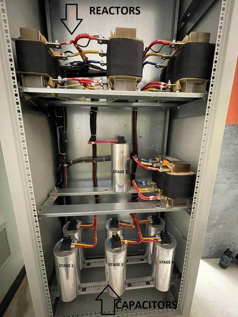
Figure 10 – Connection of Capacitors and Reactors in a Capacitor Bank
6.1 The Fatal Error of Bypassing Reactors
When a detuning reactor fails, perhaps burning out a winding, it leaves that specific capacitor step useless. A highly common, and highly dangerous, mistake made by field technicians under pressure from management to “get the power factor back up” is to bypass the damaged reactor.
They will disconnect the heavy wires from the burnt reactor and bolt them directly to the capacitor, effectively turning that single step into a standard, un-detuned capacitor.
Because detuned capacitors are typically rated for higher voltages (e.g., 525V) to handle the voltage boost from the reactor, they might survive the overvoltage briefly, but the sheer thermal mass of the harmonic current will cause the dielectric to boil within hours. The capacitor will violently rupture.
Remember, never, under any circumstances, alter the LC topology of a step! If a reactor is burnt, physically lock out that specific contactor so the step cannot be used, order the exact manufacturer replacement reactor, and run the facility at a slightly lower power factor until the correct repair can be made.
Further Study – Practical approach in design and installation of detuned capacitor banks
Practical approach in design and installation of detuned capacitor banks
7. Environmental & Physical Diagnostics
Electrical troubleshooting often ignores the physical environment, which is a critical mistake. Heat is the ultimate destroyer of power electronics. A capacitor’s lifespan is cut exactly in half for every 10°C increase in ambient temperature above its rated limit. In a detuned system, the iron-core reactors generate thousands of watts of waste heat.
If this heat is not aggressively extracted from the cabinet, the enclosure becomes an oven, baking the sensitive capacitors positioned above.
Look down at the intake louvers at the bottom of the doors. These are fitted with fibrous filter mats to keep industrial dust out. In cement plants, paper mills, or welding shops, these filters clog completely within weeks. A clogged filter starves the cooling fans. The fans will spin rapidly, cavitating in the vacuum, but no cooling air will move across the reactors.
Pop the plastic grilles off, remove the blackened filter mats, and replace them with fresh ones. If the fans are thermostatically controlled, ensure the thermostat dial inside the panel is set to 30°C or 35°C, not left at the factory default of 50°C, which allows the panel to get far too hot before cooling initiates.
Watch Video – Capacitor Bank Detuned Reactor uneven temperature
7.1. Cleaning Conductive Grime and Tracking
Industrial air is rarely clean. It carries moisture, oil mist, metallic dust, and carbon soot. Over months of operation, the cooling fans pull this contaminated air through the cabinet, depositing a fine layer of grime over every internal component. When this grime mixes with high humidity during a cold factory night, it becomes slightly conductive.
This creates microscopic electrical paths across the surfaces of the plastic insulators, a phenomenon known as creepage.
Troubleshooting requires rigorous cleaning. You cannot simply blow this grime off with compressed air; that just moves the conductive dust into the contactor mechanisms. You must use an industrial-grade, non-conductive dielectric solvent spray and clean microfiber cloths. Wipe down the tops of all capacitors, the faces of all contactors, and every single busbar insulator.
If you find deep carbon tracking that cannot be wiped away, that insulator is permanently compromised and must be unbolted and replaced before the panel is re-energized.
Good Reading – Twenty Switchgear Design Flaws That Drive Operators Crazy
8. Modern Grid Troubleshooting (Solar & Unbalance)
The electrical grid is evolving rapidly, and older PFC panels were not designed for the modern realities of distributed energy resources. The most confusing troubleshooting scenarios arise when a facility installs a large rooftop Solar Photovoltaic (PV) array.
Suddenly, the older PFC panel that worked perfectly for ten years begins throwing continuous errors, shutting down entirely, and the facility starts receiving utility penalties. Technicians will often spend days testing capacitors and CT wiring, finding nothing broken.
Standard solar inverters, however, only output Active Power (kW). They do not supply the Reactive Power (kVAr) required to keep the facility’s idle transformers and baseline loads magnetized. Therefore, the facility is exporting kW while simultaneously importing kVAr from the utility.
When a standard PFC controller sees the active current flowing backward, it assumes the CT was installed backward. It throws an “Export Error” and shuts down to protect itself, dropping all compensation exactly when the baseline inductive load needs it most. The physical solution is upgrading the panel’s “brain” to a modern 4-Quadrant controller that understands bi-directional power flow.
Figure 11 – Left: Solar PV inverters on a factory roof; Right: A standard PFC controller showing an error state

8.1 Diagnosing Single-Phase Unbalance
Standard industrial PFC banks use a single Current Transformer (usually mounted on L1) and switch three-phase capacitors. The controller mathematically assumes that whatever inductive load it sees on L1 is perfectly mirrored on L2 and L3. In heavy industries with three-phase motors, this assumption is generally correct.
However, if you are troubleshooting a commercial building, a hospital, or a data center, this assumption is fatally flawed.
To diagnose this, you must connect a 3-phase Power Quality Analyzer to the main incoming supply. Do not look at the total aggregate power factor. Look at the individual vector screens for L1, L2, and L3. If you see L1 at 0.82 Inductive, L2 at 0.95 Capacitive, and L3 at 0.90 Inductive, a standard panel cannot fix this grid. No amount of tweaking the controller will work.
You must advise the client that they require a specialized “unbalanced” PFC system that uses three individual CTs and switches single-phase capacitors independently per phase.
Figure 12 – Fluke Power Quality Analyzer recommended for Diagnosing

9. Establishing a Diagnostic Maintenance Routine
Troubleshooting is inherently reactive, meaning that you are called when something is already broken, money is being lost to utility penalties, and the equipment is heavily damaged. The ultimate goal of a field technician should be to transition the facility from reactive troubleshooting to proactive diagnostic maintenance.
A PFC bank requires an annual, deeply invasive physical inspection to catch degradation before it causes an arc flash or a system lockout.
Most importantly, the LCR meter capacitance readings for every can must be logged.
By comparing this year’s microfarad readings to last year’s, you can trend the exact degradation curve of the capacitors. If Step 3 degraded by 2% in year one, 3% in year two, and 8% in year three, you know definitively that Step 3 will fail before year four. You replace it during the scheduled downtime, entirely eliminating the emergency troubleshooting callout.
Practical troubleshooting is about mastering the tools, understanding the physical signs of stress, and documenting the decay of the system over time.
Further Study[/highlight2] – Capacitor banks protection, cautions and maintenance tips
Inspection and maintenance of capacitor banks (recommended practices)
9.1 Essential Tool Checklist for the Field
To execute the diagnostic procedures detailed in this manual, a technician cannot rely on a basic toolkit. Arriving at a facility with only a standard voltage tester and a set of screwdrivers guarantees an inaccurate diagnosis and extreme personal danger.
The field vehicle must be stocked with specific, high-tier diagnostic equipment calibrated for the harsh environment of reactive power compensation.
Furthermore, an industrial-grade infrared thermal camera is non-negotiable for identifying loose connections and failing reactors under load. A 3-phase Power Quality Analyzer is required for deep diagnostics involving harmonics and load unbalance.
Finally, your safety kit must include a certified high-voltage shorting wand with an internal discharge resistor, Class 0 dielectric gloves with current test dates, and full Category 2 arc flash apparel. Without these tools, you are guessing, and guessing in a high-capacity PFC panel leads to catastrophic failure.
Suggested Guide (PDF) – Electrical Inspection Checklists (Checking, Verifying and Reviewing Electrical Installations)
Electrical Inspection Checklists (Checking, Verifying and Reviewing Electrical Installations)
9.2 The Final Walk-Away Verification
The final, and arguably most important, practical step in any troubleshooting intervention occurs right before you leave the site. Many technicians make the mistake of replacing a blown fuse or a burnt contactor, turning the main breaker back on, seeing the controller screen light up, and immediately driving away. They assume the repair was successful because power was restored to the panel.
You must perform a dynamic walk-away verification. Once the panel is closed and energized, stand in front of the controller. Put it in Auto mode. You must wait and watch the panel perform at least three full compensation cycles based on the facility’s live load.
Watch the controller recognize a drop in power factor, listen for the specific contactor you repaired to pull in, and verify on the screen that the total Reactive Power (kVAr) drops and the Power Factor improves toward 1.00.
Only when you have physically witnessed the system correctly identify a load, switch the appropriate step, successfully correct the vector, and remain stable without hunting or throwing an error code, can you safely close out the work order and leave the facility.
Recommended Course – Practical Course for Designing LV Distribution Systems in Houses and Commercial Buildings

10. Final Troubleshooting Notes
Troubleshooting LV Reactive Power Compensation systems in the field is a rigorous, demanding discipline. It requires a technician to bridge the gap between what the automated controller thinks is happening and what the physical laws of electricity are actually doing inside the copper and aluminum components.
By abandoning heavy theory and focusing on exact meter placements, thermal signatures, visual degradation cues, and precise mathematical field checks against real-time voltages, a technician can rapidly isolate faults.
By strictly adhering to these practical steps, you ensure both your own survival and the reliable, penalty-free operation of the facility’s electrical grid.
11. Attachment (PDF): Impact of Restricted Earth Fault Relays on Protection Stability in Shunt Capacitor Banks
Download: Impact of Restricted Earth Fault Relays on Protection Stability in Shunt Capacitor Banks (for premium members only):
Related electrical guides & articles







Edvard Csanyi
Hi, I'm an electrical engineer, programmer and founder of EEP - Electrical Engineering Portal. I worked twelve years at Schneider Electric in the position of technical support for low- and medium-voltage projects and the design of busbar trunking systems.I'm highly specialized in the design of LV/MV switchgear and low-voltage, high-power busbar trunking (<6300A) in substations, commercial buildings and industry facilities. I'm also a professional in AutoCAD programming.
Profile: Edvard Csanyi