
Estimated Study Time: 53 minutes
What is a Turnkey Substation?
A Turnkey Substation is a substation that is designed, constructed, and commissioned by a Service Provider according to the specifications established by the Customer. A Service Provider is an entity (business) that provides services to other entities (companies). The Customer, or Asset Owner, typically refers to the entity—such as a public or private utility, industrial or commercial client, or cooperative—that holds regulatory and financial accountability for the asset.
 Technical Documentation for a Turnkey Substation
So, what does it mean a “turnkey” word? As a common usage the word turnkey refers to something that is ready for immediate use, such as requesting a Service Provider to perform or supply all required work to the final stage, before handing it over to the Customer.
In Construction, the term “turnkey” means a method of construction whereby the Service Provider assumes total responsibility from design to completion of the project.
In a full turnkey contract for a substation, the Service Provider will do all the work and provide all the materials, tools, labor, supervision, transportation, administration, training, and other services or items needed to finish and deliver the substation to the Customer, fully tested, integrated, and operational. The work must be done in accordance with all laws, national and international standards, and local and environmental regulations, as well as the “Customer’s Requirements.”
Production of comprehensive technical and commercial/financial documents for a substation turnkey project by the Customer before the tendering process is essential for the success of the project.
For an “in-house” project, the Customer’s engineering staff would not require detailed technical documentation for the project, since they are very familiar with the Customer’s requirements. Therefore, the time and effort required to produce such documentation for an “in-house” project is minimal.
In contrast, if the Customer decides to go with a “turnkey” project, the technical documentation must be substantially more extensive in order to express all of the Customer’s requirements to the service provider. It must also include a comprehensive list of the Customer’s equipment specs and design requirements, which the Service Provider must adhere to throughout the project.
These Customers may wish to create a precise specification based on previous experience and the availability of their own detailed standards and specifications. Such a thorough specification will include very specific requirements for the Service Provider to meet.
With the deregulation of the power industry, the number of substation customers has expanded dramatically. However, the majority of these new customers lack the necessary background expertise, technical documentation, and know-how to provide accurate and complete technical documentation for a substation project.
This technical article outlines the essential technical specifications that must be incorporated into the technical documentation for a “turnkey” substation project.
- Technical Specification for the Turnkey Substation
- Generally Accepted Requirements:
- Major Substation Equipment and Ratings
- General Design Requirements
- Civil and Structural Works
- Mechanical Works
- Buildings Associated With the Substation
- Electrical Works:
- Protection & Control Design Requirements
- Telecommunication Requirements
- Testing Requirements
- Training Requirements
- Specification of Building(s) to be Installed in the Substation
- Environmental And Safety Specification:
- Major Equipment Specifications
- Conclusions
- BONUS (PDF) 🔗 Download ‘A Guide to Broad Understanding of How Electric Power is Generated, Transmitted, Distributed, and Used’
1. Technical Specification for the Turnkey Substation
The Technical Specification document must encompass all technical requirements that the Customer intends to communicate to the Service Provider. The Technical Specification should generally include the following principal sections:
1.1 Generally Accepted Requirements
This section of Technical Sepcification must present a comprehensive overview of the project, focusing on the following issues:
1.1.1 Substation Project Description
The Substation Project Description outlines the project’s details, key characteristics, and the deliverables expected from the Service Provider. For a distribution substation, the description must encompass:
- Available land area for the substation,
- High and low voltage of the substation,
- Number of incoming high voltage lines (and their length),
- Number of feeders expected to deliver distribution power and maximum short circuit level acceptable by the distribution customers,
- Installed MVA in the substation,
- Projected ultimate short circuit level,
- Delivery mode of the high/low voltage (by cable or overhead lines),
- Preference for the switchgear (GIS, metalclad switchgear or AIS).
Information may comprise a proposed single-line schematic, but must encompass details regarding protection, control, metering requirements, and communication methods (e.g., microwave, fiber optics, telephone lines, etc.).
This section must include any information important to the Customer regarding the location of the new substation or existing facilities if the project involves refurbishment or retrofitting of an existing site.
If not all information is accessible, the Customer should specify in the document which partner in the project will be responsible for obtaining it.
Good Reading – The life of a power substation project: Design, construction, erection and commissioning
The life of a power substation project: Design, construction, erection and commissioning
1.1.2 Site Location and Environmental Data
This section presents the data related to the exact location of the future substation and provides the environmental data needed for the Service Provider to perform the work.
The Environmental Data should contain, at a minimum the following information:
Table 1 – Environmental data for the future substation
| Condition | Value |
| Altitude Above Sea Level | m |
| Average Annual Rainfall | mm |
| Extreme Rainfall | mm |
| Max. Relative Humidity | % |
| Min. Relative Humidity | % |
| Max. Outdoor Temperature | °C (dry bulb) |
| Max. Outdoor Temperature | °C (wet bulb) |
| Max Daily Average Outdoor Temperature | °C (dry bulb) |
| Min. Outdoor Temperature | °C (dry bulb) |
| Pollution (ref. To IEC/TR 60815 or C57.19.100) | salt, particles, etc. |
| Hourly Wind Pressure 1/30 | kPa |
| Hourly Wind Pressure 1/100 | kPa |
| Snow Load | kPa |
| Snowfall (maximum drift and cross depth) | mm |
| Ice Load (radial thickness) | mm |
| Max Solar Constant | kW/m2 |
| Rain Load | kPa |
| Seismic Data Za, Zv, v | G |
1.1.3 Scope Of Work
This part outlines what the Service Provider and the Customer are responsible for when it comes to the Scope of Work and where the lines between their responsibilities end. As per the Scope of Work, Technical Specification, Commercial Conditions and Terms, and other documents that are part of the tendering paperwork, the project should be carried out as a turnkey contract.
The Service Provider should be in charge of:
- Design,
- Engineering,
- Fabrication,
- Supply,
- Delivery,
- Erection,
- Installation,
- Required system studies,
- Training of staff,
- Testing commissioning,
- Field verification of the complete substation.
The part about the environment is a very important part of the Scope of Work. These days, following the rules about the environment is important, and it takes a lot of work to do so.
The following list gives a general idea of the environmental tasks and services that are needed for a power project:
- Environmental Assessment (Environmental Study report),
- Acoustic Assessment,
- Certificate of Approval for Noise,
- Certificate of Approval for Drainage,
- Site Approval,
- Chemical Soil Investigation,
- Environmental Specification for Construction,
- Environmental Monitoring During Construction
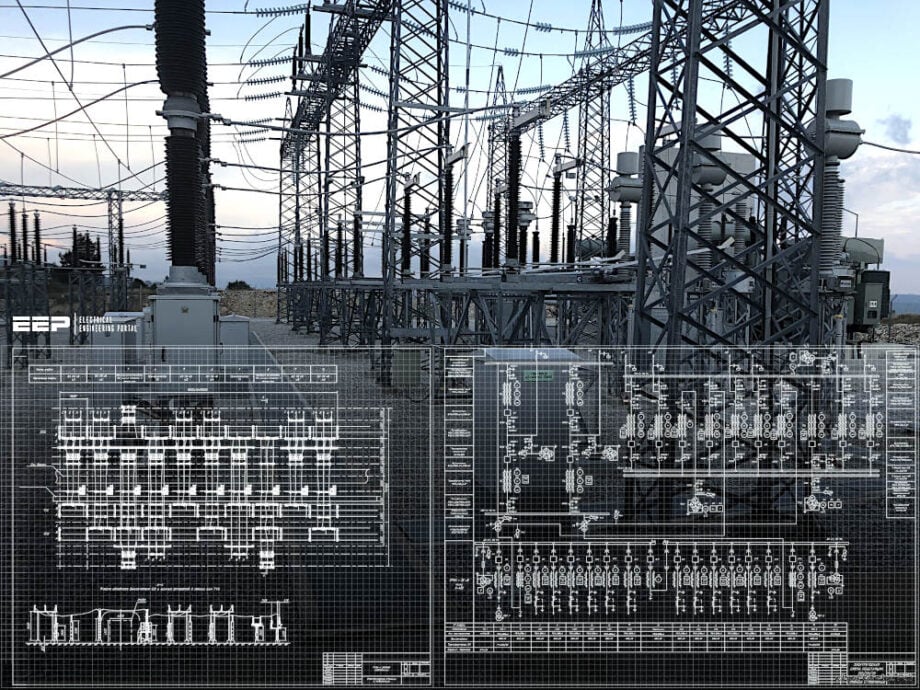
Figure 1 – Drafting the layout and arrangement drawing of 33/11 kV distribution substation

1.1.4 Project Schedule
The Service Providers need to stick to the preliminary project schedule that is part of the Project timeline. For the substation to be ready for “in-service” date, it also tells you when to put in the Critical Path Method (CPM) Work Control Schedule.
This includes a detailed plan for the project and the production of major equipment, a plan for factory inspections, a plan for design and production tests, a construction plan and list of drawings, as well as a list of the main things that the Service Provider’s civil/structural, mechanical, and electrical departments need to do to finish installing the substation.
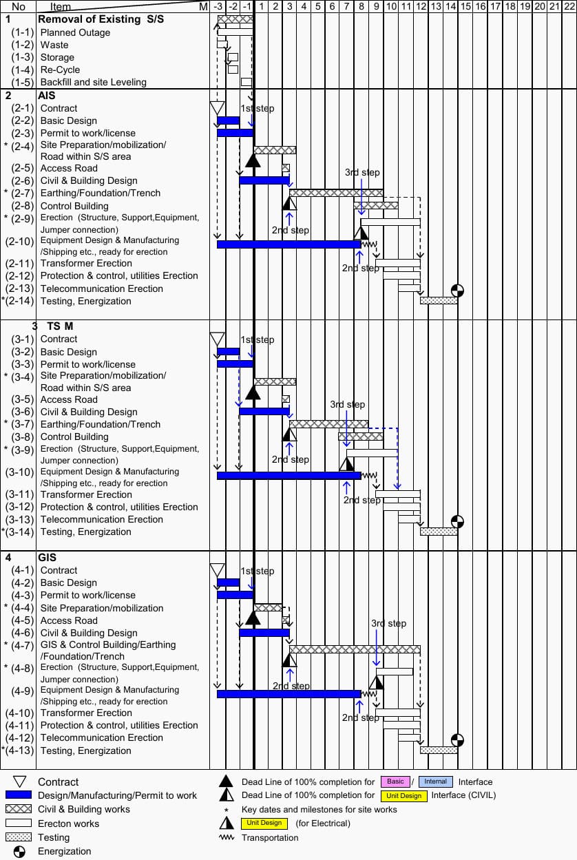
Figure 2 – An example of time schedule for the Turnkey substation project
1.1.5 Quality Control And Assurance
This section encompasses the requisite standards of quality assurance that Service Providers must adhere to. The Service Providers are typically required to submit a comprehensive Quality Assurance Manual with their proposal, including the quality assurance methods frequently implemented at their facilities.
The Service Provider must present a Quality Plan for the proposed delivery, which shall delineate the processes and procedures that the successful bidder will employ to ensure compliance with the contract criteria.
Further Study – Procedures and activities during the design and tendering phase of HV project engineering
Procedures and activities during the design and tendering phase of HV project engineering
1.1.6 Spare Parts And Serviceability
It specifies the Customer’s requirements related to what spare parts should be part of the contract, their availability for the required period of time and what level of service will be required and for how long from the successful bidder.
1.1.7 Drafting And Documentation
Drafting And Documentation section specifies the level of technical documentation related to Scope of Work.
The documentation should consist of all relevant:
- Civil drawings,
- Structural drawings,
- Mechanical drawings,
- Electrical drawings,
- Telecom drawings,
- All equipment manufacturer drawings,
- Bills of material,
- Cable list,
- Technical description and applicable calculations,
- Inspection, test & acceptance plan and
- Installation, operating and maintenance instruction for equipment.
This section also specifies the drafting practices, drawing review process to be followed by the Service Provider and the way “As Built” drawings and documents are to be handled.
Related electrical guides & articles


Edvard Csanyi
Hi, I'm an electrical engineer, programmer and founder of EEP - Electrical Engineering Portal. I worked twelve years at Schneider Electric in the position of technical support for low- and medium-voltage projects and the design of busbar trunking systems.I'm highly specialized in the design of LV/MV switchgear and low-voltage, high-power busbar trunking (<6300A) in substations, commercial buildings and industry facilities. I'm also a professional in AutoCAD programming.
Profile: Edvard Csanyi
