
Estimated Study Time: 16 minutes
Type tests defined in IEC 61439
Certification of distribution assemblies is defined by international standard IEC 61439-1. This standard provides common rules that are recognized worldwide. Compliance with the standard is certified, depending on the country or market, by a declaration of the panel builder, the design office, the installer or the user.
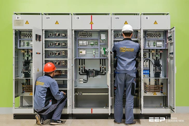 13 most important type tests of a low voltage switchgear performed in a factory (photo credit: eksiton.ru)
Just to mention before going into test, that low voltage switchgear and controlgear assemblies (Un ≤ 1000 V AC) may be used at the origin of an electrical installation with:
- Low Voltage Main switchboard (transformer area)
- Low Voltage Main Distribution Board (technical area) and
- Sub Distribution boards
Seven type tests are carried out officially on low voltage assemblies representative of the usual wiring configurations and equipment layouts. These assemblies are called ‘standard assemblies’. By definition, standard assemblies only contain layouts that have undergone type tests.
Table of contents:
They cover the following checks for type tests:
And there are also six tests designed to check the construction quality are added to the above type tests in standard IEC 61439-1.
1. Type tests
1.1 Temperature rise limits
Verification in temperature rise limits test is one of the most critical in determining the reliability and long service capability of a low voltage assembly and must not be overlooked. Excessive temperatures result in premature ageing of components and insulation, and ultimately failure.
When temperature rise verification is carried out by test, the manufacturer can select from three options to suit the design and the total time to be devoted to testing:
Option 1
The incoming circuit and at least one outgoing circuit of each rating are loaded to their rated current. If a circuit of each basic type is not included in the test, further tests are carried out until one outgoing circuit of each type has been included. This approach is suitable where a specific arrangement and design of assembly is to be verified with the minimum amount of testing.
As the outgoing circuits are tested with a diversity (loading) factor of unity, it does, however, result in a more onerous test than necessary for most applications.
Option 2
Outgoing circuits are temperature rise tested individually to verify they are capable of carrying their rated current. The incoming circuit is then supplied to its rated current. This is distributed through as many outgoing circuits as practical, including one outgoing circuit of each basic type and in the most onerous configuration, with each circuit loaded to its rated current multiplied by the rated diversity (loading) factor.
Again, this test regime is only suitable for a specific arrangement and design of assembly, but it does better reflect the normal loading of an assembly.
Option 3
This alternative has been included to enable modular assembly systems to be fully verified. Horizontal busbars, vertical busbars and outgoing functional units are tested individually. The assembly as a whole is then verified as in Option 2.
Note that temperature rise tests are time consuming. A lot of time is required to connect all the circuits to be included in the test, balance the current and insert the thermocouples. Current is applied until conditions stabilize, usually around eight hours, and, in the final hours, temperatures are monitored, normally with thermocouples.
Critical areas for temperature measurement are covers, operating handles, busbars and joints, insulators, cable terminals, device and/or internal air temperatures.
1.1.1 Temperature rise test on assemblies
This test checks that assemblies operate correctly under maximum operating conditions (current, number of devices, volume of enclosure). It is used to define the heat balance data for an average temperature rise of the air in assemblies of less than 30 K and a temperature rise of the terminals of less than 70 K.
Note that temperatures rises are given in Kelvin to differentiate them from temperatures given in °C.
1.1.2 Temperature rise test on busbars
The various currents given for all the bar and distribution systems have been checked under the most severe conditions, according to the degree of ventilation of the enclosure (IP ≤ 30 and IP > 30), so that the temperature rise of the busbars does not exceed 65 K.
Go back to Table of Contents ↑
1.2 Dielectric properties
The dielectric tests check the insulation performance levels for the maximum operating voltage. They are carried out at the industrial frequency of 50 Hz and in the form of voltage waves simulating a lightning strike.
Go back to Table of Contents ↑
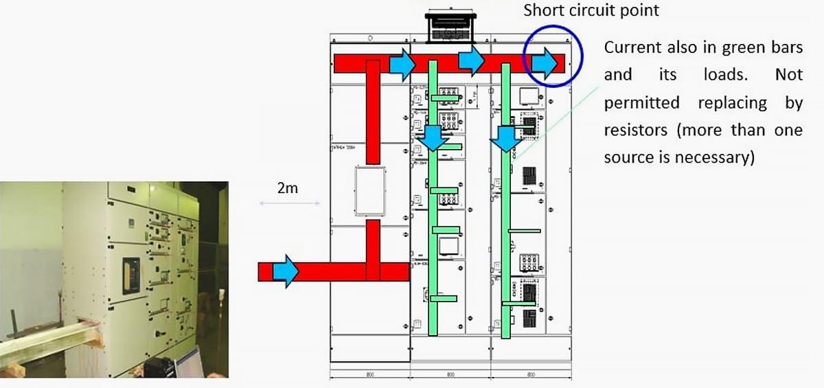
1.3 Short-circuit resistance
The tests carried out ensure the resistance of busbars and their supports, breaking and protection devices and enclosures to thermal and electrodynamic stresses.
Go back to Table of Contents ↑
1.4 Effectiveness of the protective circuit
The continuity of the protective circuit is a decisive factor for safety. It is checked in accordance with standard IEC 61439-1 at a test current of 25 A between the terminal connecting the protective conductors and all the exposed conductive parts.
The continuity of the protective circuit is also checked at a high fault current that could occur following accidental detachment of a conductor.
The protective circuits (conductors, terminals or collector bars), are sized and tested to withstand the maximum short-circuit thermal stress that could occur according to the current at the supply end of the assembly.
Go back to Table of Contents ↑
1.5 Clearances and creepage distances
The methods for measuring creepage distances and clearances in standard IEC 60664-1 are repeated in full in appendix f of standard IEC 61439-1. The distances are measured between live parts with different polarities, and also between live parts and the exposed conductive parts.
Connections, bundles of conductors and busbars must be meticulously checked.
Unsuitable connectors, bolted connections, joints and metal supports can reduce the initially planned insulation values.

Go back to Table of Contents ↑
1.6 Checking mechanical operation
In accordance with the provisions of the standard, tests are carried out on parts and devices that are not subject to any specific requirements. Correct mechanical operation is checked by 50 operating cycles on drawout racks and faceplate fixings.
Edvard Csanyi
Hi, I'm an electrical engineer, programmer and founder of EEP - Electrical Engineering Portal. I worked twelve years at Schneider Electric in the position of technical support for low- and medium-voltage projects and the design of busbar trunking systems.I'm highly specialized in the design of LV/MV switchgear and low-voltage, high-power busbar trunking (<6300A) in substations, commercial buildings and industry facilities. I'm also a professional in AutoCAD programming.
Profile: Edvard Csanyi
