
Estimated Study Time: 26 minutes
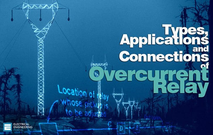
Overcurrent Relay
Distribution systems are susceptible to overcurrent flow within its components. Overcurrent may arise from abnormal system conditions, including overloads and short-circuit failures, or from typical system conditions, such as transformer inrush current and motor initiation. Consequently, under typical system conditions, technologies like as demand-side management, load shedding, and soft motor starting may be utilized to prevent overloads.
Moreover, distribution systems are outfitted with protective relays that activate mechanisms to ensure switching equipment reacts solely to atypical system conditions.
The relay is linked to the circuit requiring protection through current transformers (CTs) and voltage transformers (VTs) in accordance with the specified protective function. For example, directional overcurrent prevention employs both current transformers (CTs) and voltage transformers (VTs), whereas earth-fault protection utilizes solely current transformers (CTs).
Note that relays must be energized to function. The energy may be supplied by the monitored circuit or by utilizing energy-storage systems, such as capacitor trip devices for small low-voltage systems or battery packs for big switchgear.
Providing energy straight from the monitored circuit poses a risk of relay malfunction due to potential unexpected voltage drops in the system.
- Types of protection:
- Various types of Line Faults
- Overcurrent Relay Purpose and Ratings
- Difference between Overcurrent and Overload protection
- Types of Overcurrent Relay:
- Application of Overcurrent Relay
Types of protection
Protection schemes can be divided into two major groupings:
- Unit schemes
- Non-unit schemes
1. Unit Type Protection
Unit type schemes protect a specific area of the system, i.e., a transformer, transmission line, generator or bus bar.
Any deviation from this must indicate an abnormal current path. In these schemes, the effects of any disturbance or operating condition outside the area of interest are totally ignored and the protection must be designed to be stable above the maximum possible fault current that could flow through the protected area.
2. Non unit type protection
The non-unit schemes, while also intended to protect specific areas, have no fixed boundaries. As well as protecting their own designated areas, the protective zones can overlap into other areas. While this can be very beneficial for backup purposes, there can be a tendency for too great an area to be isolated if a fault is detected by different non unit schemes.
The most simple of these schemes measures current and incorporates an inverse time characteristic into the protection operation to allow protection nearer to the fault to operate first.
- Time graded overcurrent protection
- Current graded overcurrent protection
- Distance or Impedance Protection
2.1 Overcurrent protection
This is the simplest of the ways to protect a line and therefore widely used.
It owes its application from the fact that in the event of fault the current would increase to a value several times greater than maximum load current. It has a limitation that it can be applied only to simple and non costly equipments.
2.2 Earth fault protection
The general practice is to employ a set of two or three overcurrent relays and a separate overcurrent relay for single line to ground fault. Separate earth fault relay provided makes earth fault protection faster and more sensitive.
Earth fault current is always less than phase fault current in magnitude.
Therefore, relay connected for earth fault protection is different from those for phase to phase fault protection.
Various types of Line Faults
| No | Type of Fault | Operation of Relay |
| 1 | Phase to Ground fault (Earth Fault) | Earth Fault Relay |
| 2 | Phase to Phase fault Not with Ground | Related Phase Overcurrent relays |
| 3 | Double phase to Ground fault | Related Phase Overcurrent relays and Earth Fault relays |
Overcurrent Relay Purpose and Ratings
A relay that operates or picks up when it’s current exceeds a predetermined value (setting value) is called Overcurrent Relay.
For feeder protection, there would be more than one overcurrent relay to protect different sections of the feeder. These overcurrent relays need to coordinate with each other such that the relay nearest fault operates first.
Use time, current and a combination of both time and current are three ways to discriminate adjacent overcurrent relays.
OverCurrent Relay gives protection against:
Overcurrent includes short-circuit protection, and short circuits can be:
- Phase faults
- Earth faults
- Winding faults
Short-circuit currents are generally several times (5 to 20) full load current. Hence fast fault clearance is always desirable on short circuits.
Primary requirement of Overcurrent protection
The protection should not operate for starting currents, permissible overcurrent, current surges. To achieve this, the time delay is provided (in case of inverse relays).
Overcurrent relay is a basic element of overcurrent protection.
Purpose of overcurrent Protection
These are the most important purposes of overcurrent relay:
- Detect abnormal conditions
- Isolate faulty part of the system
- Speed Fast operation to minimize damage and danger
- Discrimination Isolate only the faulty section
- Dependability / reliability
- Security / stability
- Cost of protection / against cost of potential hazards
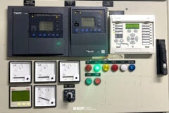
Figure 1 – Directional overcurrent protection relay

Overcurrent Relay Ratings
In order for an overcurrent protective device to operate properly, overcurrent protective device ratings must be properly selected. These ratings include voltage, ampere and interrupting rating.
Current limiting can be considered as another overcurrent protective device rating, although not all overcurrent protective devices are required to have this characteristic
Voltage Rating: The voltage rating of the overcurrent protective device must be at least equal to or greater than the circuit voltage. The overcurrent protective device rating can be higher than the system voltage but never lower.
Ampere Rating: The ampere rating of a overcurrent protecting device normally should not exceed the current carrying capacity of the conductors As a general rule, the ampere rating of a overcurrent protecting device is selected at 125% of the continuous load current.
Difference between Overcurrent and Overload protection
Overcurrent protection protects against excessive currents or currents beyond the acceptable current ratings, which are resulting from short circuits, ground faults and overload conditions. While, the overload protection protects against the situation where overload current causes overheating of the protected equipment.
The overcurrent protection is a bigger concept So that the overload protection can be considered as a subset of overcurrent protection.
The overcurrent relay can be used as overload (thermal) protection when protects the resistive loads, etc., however, for motor loads, the overcurrent relay cannot serve as overload protection Overload relays usually have a longer time setting than the overcurrent relays.
Suggested Study – An example of transformer overload and short circuit protection
An example of transformer overload and short circuit protection
Types of Overcurrent Relay
These are the types of overcurrent relay:
- Instantaneous Overcurrent (Define Current) Relay
- Define Time Overcurrent Relay
- Inverse Time Overcurrent Relay (IDMT Relay)
- Moderately Inverse
- Very Inverse Time
- Extremely Inverse
- Directional overcurrent Relay
1. Instantaneous Overcurrent relay (Define Current)
Definite current relay operate instantaneously when the current reaches a predetermined value. When the current achieves or beyond the predetermined threshold, the relay operates instantaneously, as illustrated in the characteristic curve below. The relay configuration is modified according on its position within the network. The value decreases as the relay point is increasingly far from the source.
For example, the overcurrent relay at the receiving end of a distribution feeder will for a current that is lower than that at the sending end, particularly when the feeder impedance is significant.
When the feeder impedance is significantly lower than the upstream network impedance, it becomes challenging to differentiate between fault currents at both ends, resulting in inadequate discrimination and minimal selectivity at higher short-circuit current levels.
Poor discrimination and limited choice are regarded as drawbacks of this form of protection. Conversely, when the feeder impedance or the impedance of the protected element is elevated, instantaneous protection has the benefits of minimizing the relay’s running time for critical faults and preventing the loss of selectivity in systems employing relays with varying characteristics.
For distribution lines terminated by MV/LV transformers, the setting is established at 50% of the maximum short-circuit current at the CT connection point or within the range of 6 to 10 times the maximum circuit rating. When the instantaneous overcurrent relay is positioned on the primary side of the transformer, its setting ranges from 1.25 to 1.50 times the short-circuit current entering the bus bar on the low-voltage (LV) side, as referenced to the high-voltage (HV) side.
This number is adequate to maintain coordination with the elevated current experienced owing to magnetic inrush when activating the transformer.
Figure 2 – Instantaneous Overcurrent Relay – Definite Current

- Operates in a definite time when current exceeds its Pick-up value.
- Its operation criterion is only current magnitude (without time delay).
- Operating time is constant.
- There is no intentional time delay.
- Coordination of definite-current relays is based on the fact that the fault current varies with the position of the fault because of the difference in the impedance between the fault and the source
- The relay located furthest from the source operate for a low current value
- The operating currents are progressively increased for the other relays when moving towards the source.
- It operates in 0.1s or less
Application: This type is applied to the outgoing feeders.
Watch Lesson – Directional Overcurrent Relay
2. Definite Time Overcurrent Relays
In case of definite-time overcurrent relays, two conditions must be satisfied for operation (tripping), current must exceed the setting value and the fault must be continuous at least a time equal to time setting of the relay.
Definite-time overcurrent relays, a type of protect, has an operating time frame that remains constant regardless of the current magnitude after a specific threshold is attained.
This relay type features a current setting, sometimes referred to as the pickup, plug, or tap setting, to determine the current threshold at which the relay activates, together with a time dial setting to specify the precise duration of relay activity.
The drawback of this protection method is that a short-circuit fault near the source may be resolved in a comparatively prolonged duration, notwithstanding its maximum current magnitude.
Figure 3 – Definite time of overcurrent relay

Modern relays may contain more than one stage of protection each stage includes each own current and time setting.
- For Operation of Definite Time Overcurrent Relay operating time is constant
- Its operation is independent of the magnitude of current above the pick-up value.
- It has pick-up and time dial settings, desired time delay can be set with the help of an intentional time delay mechanism.
- Easy to coordinate.
- Constant tripping time independent of in feed variation and fault location.
Drawback of Relay:
- The continuity in the supply cannot be maintained at the load end in the event of fault.
- Time lag is provided which is not desirable in on short circuits.
- It is difficult to co-ordinate and requires changes with the addition of load.
- It is not suitable for long distance transmission lines where rapid fault clearance is necessary for stability.
- Relay have difficulties in distinguishing between Fault currents at one point or another when fault impedances between these points are small, thus poor discrimination.
Application:
Definite time overcurrent relay is used as:
- Back up protection of distance relay of transmission line with time delay.
- Back up protection to differential relay of power transformer with time delay.
- Main protection to outgoing feeders and bus couplers with adjustable time delay setting.
3. Inverse Time Overcurrent Relays (IDMT Relay)
In this type of relays, operating time is inversely changed with current. So, high current will operate overcurrent relay faster than lower ones. There are standard inverse, very inverse and extremely inverse types. Discrimination by both ‘Time’ and ‘Current’. The relay operation time is inversely proportional to the fault current.
Inverse Time relays are also referred to as Inverse Definite Minimum Time (IDMT) relay.
Figure 4 – Inverse Definite Minimum Time (IDMT)
")
The inverse-time overcurrent relays function more rapidly as the current rises. Their feature is illustrated in the figure above. They are offered with inverse, highly inverse, and extremely inverse-time properties to meet the specific application needs.
Refer to Figure 5.
The working times of both overcurrent definite-time relays and overcurrent inverse-time relays must be configured to ensure that the relay nearest to the fault trips before to any other protective devices. This is referred to as time grading. The disparity in operation time between two successive relays at an identical fault level is termed the “discrimination margin.” The typical response time is 0.25–0.4 seconds for electromagnetic and static relays, and 0.2 seconds for digital relays.
Figure 5 – Typical relay time-current characteristics

Where: (A) Inverse; (B) very inverse; (C) extremely inverse; (D) instantaneous. TD = relay time dial setting
The calibration process of definite-time and inverse-time relays involves establishing two parameters: the time dial setting and the pickup setting. The time dial setting, also known as the time multiplier, is established for the various relays within the system by specifying the time delay of each relay while considering the time grading and discriminating margin. The pickup setting determines the relay’s pickup current, which is exceeded by the fault current.
The operating time of an overcurrent relay can be moved up (made slower) by adjusting the ‘time dial setting’. The lowest time dial setting (fastest operating time) is generally 0.5 and the slowest is 10.
- Operates when current exceeds its pick-up value.
- Operating time depends on the magnitude of current.
- It gives inverse time current characteristics at lower values of fault current and definite time characteristics at higher values
- An inverse characteristic is obtained if the value of plug setting multiplier is below 10, for values between 10 and 20 characteristics tend towards definite time characteristics.
- Widely used for the protection of distribution lines.
Based on the inverseness it has three different types:
Figure 6 – Inverse types

3.1. Normal Inverse Time Overcurrent Relay
The accuracy of the operating time may range from 5 to 7.5% of the nominal operating time as specified in the relevant norms. The uncertainty of the operating time and the necessary operating time may require a grading margin of 0.4 to 0.5 seconds.
Normal inverse time Overcurrent Relay is relatively small change in time per unit of change of current.
Application:
Most frequently used in utility and industrial circuits. especially applicable where the fault magnitude is mainly dependent on the system generating capacity at the time of fault.
3.2. Very Inverse Time Overcurrent Relay
- Gives more inverse characteristics than that of IDMT.
- Used where there is a reduction in fault current, as the distance from source increases.
- Particularly effective with ground faults because of their steep characteristics.
- Suitable if there is a substantial reduction of fault current as the fault distance from the power source increases.
- Very inverse overcurrent relays are particularly suitable if the short-circuit current drops rapidly with the distance from the substation.
- The grading margin may be reduced to a value in the range from 0.3 to 0.4 seconds when overcurrent relays with very inverse characteristics are used.
- Used when Fault Current is dependent on fault location.
- Used when Fault Current independent of normal changes in generating capacity.
3.3. Extremely Inverse Time Overcurrent Relay
- It has more inverse characteristics than that of IDMT and very inverse overcurrent relay.
- Suitable for the protection of machines against overheating.
- The operating time of a time overcurrent relay with an extremely inverse time-current characteristic is approximately inversely proportional to the square of the current
- The use of extremely inverse overcurrent relays makes it possible to use a short time delay in spite of high switching-in currents.
- Used when Fault current is dependent on fault location
- Used when Fault current independent of normal changes in generating capacity.
Application:
- Suitable for protection of distribution feeders with peak currents on switching in (refrigerators, pumps, water heaters and so on).
- Particular suitable for grading and coordinates with fuses and re closes
- For the protection of alternators, transformers. Expensive cables, etc.
3.4. Long Time Inverse Overcurrent Relay
The main application of long time overcurrent relays is as backup earth fault protection.
4. Directional Overcurrent Relays
When the power system is not radial (source on one side of the line), an overcurrent relay may not be able to provide adequate protection. This type of relay operates in on direction of current flow and blocks in the opposite direction. Three conditions must be satisfied for its operation: current magnitude, time delay and directionality.
In short, the directionality of current flow can be identified using voltage as a reference of direction.
Further Study – The essentials of directional overcurrent protection in electrical power grid
The essentials of directional overcurrent protection in electrical power grid
Application of Overcurrent Relay
Motor Protection:
- Used against overloads and short-circuits in stator windings of motor.
- Inverse time and instantaneous overcurrent phase and ground
- Overcurrent relays used for motors above 1000 kW.
Transformer Protection:
- Used only when the cost of overcurrent relays are not justified.
- Extensively also at power-transformer locations for external-fault back-up protection.
Line Protection:
- On some sub transmission lines where the cost of distance relaying cannot be justified.
- primary ground-fault protection on most transmission lines where distance relays are used for phase faults.
- For ground back-up protection on most lines having pilot relaying for primary protection.
Distribution Protection:
Overcurrent relaying is very well suited to distribution system protection for the following reasons:
- It is basically simple and inexpensive.
- Very often the relays do not need to be directional and hence no PT supply is required.
- It is possible to use a set of two O/C relays for protection against inter-phase faults and a separate Overcurrent relay for ground faults.
Recommended Course – Overcurrent Protection Course: Principles, Relays, Schematics and Settings
Overcurrent Protection Course: Principles, Relays, Schematics and Settings
Related electrical guides & articles


Jignesh Parmar
Electrical Middle management professional having more than 22 years rich and dynamic experience in Project Execution / Project Management / Designing / Maintenance diversifies from Electrical Power Transmission (400KV/220KV/66KV)- Distribution(11KV/220V) to Lifts-HVAC-Ventilation-Fire Fighting-Fire Alarm-Lifts-CCTV-Stack Parking Works (High Rise Buildings, Townships, Shopping Complex, Commercial Complex, School, Temple).Profile: Jignesh Parmar

How to calculate the three stages of Overcurrent ,Thnks
Sir, please advise the Over current protection settings and Thermal overload protection for 2MW 3.3KV Gen set. The relai will be used as Micom P-127 relay, I have set the In (Over current) 6In with 30 milli secs (Curve IDMT) and Thermal over load is 100% IN =1In with time of 60 minutes. Is it correct oor any changings are required. Pl.advise sir,
Please let me know that this 7SJ614 can be used in the Switchgear Panels (33kV and 13.8kV) for ARC FLASH Protection by sensing light, Pressure and heat .
Your early reply will be highly appreciated.
Dear Sirs,
I hope you can make an article as well comparing IEC and ANSI curves thank you!
Hi to all engineers in here may I ask for a LINE PROTECTION CALCULATION and Over Current protection calculations?
Thank you.
Best regards,
MArk
Single phase fault currents are NOT always lower than Phase fault currents. It depends on the zero sequence impedance of the system.
dear sir please inform me about the when 132kv line frequancy higt what we do and what is excitation have a book plz send me in my email
Thank you
its very helpful thank you.
Hi Bro.
Hi all Engineer
First of all i would like to thanks you very very much, your lesseon are so valuable
To introduce myself, my name Binh, i am Vietnamese, i work for shipyard that many electrical issue i met everyday make me many questions about it
Could you please agree to put myself in your group that can help me to follow all comments from all engineers and also i can send my question on it
Many thanks/ Binh
why psm calculation is important if we are using plug setting ?iam so much confussed about this topic?
Good Day, the ANSI codes for the instantaneous / definite time and IDMT relays are 50 / 51. The other terminology used for overcurrent is hi-set and low-set. what are the differences between definite time and IDMT compared to hi-set and low-set overcurrent. Is it correct to say that IDMT is low-set and Instantaneous is hi-set?
IDMT is low set. Instantaneous, in old days used to be high set (i.e., trips without delay for respective plug setting). Now a days we have options to set many stages of fault current for tripping.
Eg., upto 1.0 In, you may select a curev like NI-3.0, for secoond stage-I>> you can again select curve or give defenite tme tripping. Then you will have another stage-I>>> for which you will usually have only defenite time.
I’ve seen in some protection schemes for transmission lines bays they have pickup valur for I>>
I>>> and I> both are selcted oo
Why is the last point in distribution protection an advantage? Why have seperate relays when a single relay can be used to implement multiple elements such as protection against ground faults, as well as ac instantaneous overcurrent?
what is short inverse characteristics
In our co-gen Plant , we are facing the problem of frequent tripping of grid breaker on stand by earth fault protection due to 110 KV line earth fault or even due to small disturbance at 110 KV line or at 110 KV substation where we are exporting the power.
We are having one earth fault relay and one stand by earth fault relay. Please suggest us to reduce these frequent tripping of relay, what will be the characteristics of relay to be set ( definite time, normal inverse or very long inverse etc.
How we can select power transformer Rating? consider it is feeding for 4 Motor which is rated 100KW each and it has 6 times of starting current.
Very very thanks to the Resp.author. In SGP subject. It become so helpful for me.
It’s really help full site for me
Hello sir.. My name is Aidil and i am undergraduate in Bachelor degree in Electrical Engineering at Universiti Teknologi Malaysia.. I’m not understand clearly on earth fault relay.. hot its work actually?
Please develop the app at most and website too…. if it is much impressive… Any one may wud like to donate for site and app development …..make app ease for quick reference
i luv the app…..thanks a lot….
Superb andriod app thanks a lot one of the best apps in the world …knowledge treasure
sir ,
what do u mean by 1.3 secs at Ni at tms =1
sir , thank you for your information .
if you don’t mine please send me power system protection book on my mail id [email protected]
Thanks alot for the helpful information you provide
Great article. Very helpful.
its very helpful thanks
EEP Portal is Beautiful gift for all Electrical Engineers……Nothing but Knowledge treasure…Thanks a lot for educating for us.
this is awesome!!! Thank you.