
Primary and secondary windings
The primary winding is a part of the network, carrying the actual load current. The transformer’s secondary circuits usually consist of several units, each of them having its own magnetic core and winding.
The transformer has a rated current transforming ratio, like for example 200/1 A, stating the rated primary current and the corresponding rated secondary current.
For doing current transformers with multiple ratios there are two possibilities, namely:
- Primary re-connectable or
- Secondary re-connectable.
 and primary re-connectable (right) current transformer winding presentation")
Primary re-connectable means that the primary circuit connection has to be changed to change the ratio. Usually only two connection alternatives exist having a ratio of 2:1.
An example below:
200–400/1/1 A
The ratio can be selected to be either 200/1 A or 400/1 A. The selection affects all the secondary windings. The secondary core data, except for the ratio, remains the same with either of the ratio selections. The underlined value shows the presently utilized ratio.
Secondary re-connectable means that the ratio can be changed by utilizing tappings in each of the secondary cores. More than two ratio alternatives can exist, with uneven ratios.
An example below:
600/1 + 200-300-400/1/1 A
One of the cores (600/1 A) is having a fixed ratio, whereas with the two other cores the ratio can be selected by means of a secondary re-connection. The secondary core data will change along with the ratio selection. The underlined value shows the presently utilized ratio, where the selection possibility exists.


Where:
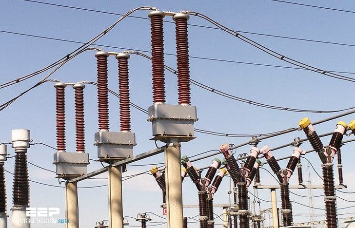
- Medium voltage terminals
- Primary winding
- Magnetic circuit
- Secondary winding
- Epoxy body
- Secondary outlets
- Base plate
- Cover of secondary terminals used for outlet sealing
With an ideal current transformer under short-circuited conditions, there is always a balance with the ampere turns, meaning that the product of primary current and primary winding turns equals the product of secondary current and secondary winding turns.
I1 × N1 = I2 × N2

Equivalent circuit
The behavior of current transformers and the conformities to basic electrical laws can be demonstrated by the use of equivalent circuit shown below.

From the above equivalent circuit, it can be seen that with a non-ideal transformer there are always some errors included in the measurement. These errors are mainly caused by the excitation current (Ie) and the load current (I2), which introduces both ratio errors and angle errors between the reduced primary current and the actual secondary current.
It can also be further observed that if the CT secondary side is left open-circuited (infinite burden connected), the whole primary current starts to excite the CT, resulting in overloading and induced dangerous voltage in the secondary terminals.
The issue is approached through an example. It is assumed here that a three-phase current transformer set, having the below shown data labels, is used for energy measurement and overcurrent protection.
200-400/1/1 A
| 1S1-1S2 | 5VA class 0.5 | Fs5 |
| 1S1-1S3 | 10VA class 0.5 | Fs5 |
| 2S1-2S2 | 10VA | 5P10 |
| 2S1-2S3 | 20VA | 5P10 |
| 12/28/75kV 50Hz | 40(1s)/100kA |
200-400/1/1A
The transformer has dual-ratio re-connection (from secondary) possibilities and two second-ary cores. The rated primary current is either 200A or 400A. The rated secondary current is 1A.
- 1S1-1S2 5VA class 0.5 Fs5
- 1S1-1S3 10VA class 0.5 Fs5
The first secondary core is for measuring. The ratio selection between 200/1A and 400/1A is made by the secondary re-connection. Connection between 1S1 and 1S2 gives a ratio of 200/1A whereas 1S1 and 1S3 gives a ratio of 400/1A.
The accuracy class of this measuring core is 0.5. To comply with this accuracy class, the transformer has to fulfill certain requirements regarding current error and phase displacement error as shown below. These limits apply to secondary burdens between 25-100% of the rated burden.

The secondary rated burden of the measurement core is changing according to the used secondary re-connection (tapping). With the highest ratio (400/1A) the rated burden is 10VA and with the lowest ratio (200/1A) the rated burden is 5VA.
Primary current of magnitude five times (Fs 5) the rated primary current causes a combined error of at least 10%. The protective feature for measurement devices is the better the lower the overcurrent limit factor is. It should be further noticed that the given overcurrent limit factor value applies with the stated rated burden and is subject to change if the actual burden differs from the rated burden.
- 2S1-2S2 10 VA 5P10
- 2S1-2S3 20 VA 5P10
The second secondary core is for protection. The ratio selection between 200/1A and 400/1A is made by the secondary re-connection. Connection between 1S1 and 1S2 gives a ratio of 200/1A whereas 1S1 and 1S3 gives a ratio of 400/1A.
The secondary rated burden of the measurement core changes according to the used secondary re-connection (tapping). With the highest ratio (400/1A) the rated burden is 20VA and with the lowest ratio (200/1A) the rated burden is 10VA.
The accuracy limit factor changes in relation to the actual connected burden. For example, if the ratio of 400/1A was used and the total connected actual burden, including all leads and connected devices, was 15VA, the accuracy limit factor would then result as follows:
20/15 × 10 ≈ 13.3 (Actual accuracy limit factor)
If the ratio of 200/1A was used instead, the actual accuracy limit factor would be:
10/15 × 10 ≈ 6.7 (Actual accuracy limit factor)
12/28/75kV
12kV is the highest voltage for the equipment (RMS value). 28kV is the rated power frequency withstanding voltage (RMS test value). 75kV is the rated lightning impulse withstanding voltage (peak test value).
40(1s)/100kA
This states the short thermal current withstanding level being 40kA/1s (RMS) and the dynamic current withstanding level being 100kA (peak value).
Reference // Distribution Automation Handbook (prototype) – ABB


Respected Sir,
May I request you to please share via email to me, your articles related to Instrument Class / Measurement Class Current Transformers, of Nominal Input Current Ratings of a] 5 Amp rms, 50 Hz or 60 Hz and b] 1 Amp rms, 50 Hz or 60 Hz. I am interested in your valuable inputs such as: 1] How to COMPLETELY Specify and 2] How to COMPLETELY Test, including Input-to-Output Phase-Angle Error. My Applications are for measuring Supply Current (Load Current) and Capacitor Current, BOTH, for my Automatic Power Factor Controller Units, where these CTs are mounted vertically and soldered on my PCB. Thanks a lot in advance for your anticipated kind advise and support. With highest-best regards & respects, – Jaykrushna P. Puranik, Nasik, Maharashtra State, INDIA.
hello Sir i just want to know how we design the insulation of current transformer by making series of capacitors
hello thanks for our information
Please add me insubscription list
I am not engineer but I intresting electric