
Estimated Study Time: 8 minutes
Underground cables
Underground cables have different technical requirements than overhead lines and have different environmental impacts. Due to their different physical, environmental, and construction needs, underground transmission generally costs more and may be more complicated to construct than overhead lines.
The design and construction of underground transmission lines differ from overhead lines because of two significant technical challenges that need to be overcome. These are:
- Providing sufficient insulation so that cables can be within inches of grounded material.
- Dissipating the heat produced during the operation of the electrical cables. The first underground transmission line was a 132 kV line constructed in 1927. The cable was fluid-filled and paper insulated. The fluid was necessary to dissipate the heat.
There are two main types of underground transmission lines currently in use. One type is constructed in a pipe with fluid or gas pumped or circulated through and around the cable in order to manage heat and insulate the cables. The other type is a solid dielectric cable which requires no fluids or gas and is a more recent technological advancement.
The common types of underground cable construction include:
- High-pressure, fluid-filled pipe (HPFF)
- High-pressure, gas-filled pipe (HPGF)
- Self-contained fluid-filled (SCFF)
- Solid cable, cross-linked polyethylene (XLPE)
High-Pressure, Fluid-Filled Pipe-Type Cable
A high-pressure, fluid-filled (HPFF) pipe-type of underground transmission line, consists of a steel pipe that contains three high-voltage conductors. Each conductor is made of copper or aluminum; insulated with high-quality, oil-impregnated kraft paper insulation; and covered with metal shielding (usually lead) and skid wires (for protection during construction).
Inside steel pipes, three conductors are surrounded by a dielectric oil which is maintained at 200 pounds per square inch (psi). This fluid acts as an insulator and does not conduct electricity. The pressurized dielectric fluid prevents electrical discharges in the conductors’ insulation. An electrical discharge can cause the line to fail. The fluid also transfers heat away from the conductors. The fluid is usually static and removes heat by conduction. In some situations the fluid is pumped through the pipe and cooled through the use of a heat exchanger. Cables with pumped fluids require aboveground pumping stations, usually located within substations.
The pumping stations monitor the pressure and temperature of the fluid. There is a radiator-type device that moves the heat from the underground cables to the atmosphere. The oil is also monitored for any degradation or trouble with the cable materials. The outer steel pipe protects the conductors from mechanical damage, water infiltration, and minimizes the potential for oil leaks. The pipe is protected from the chemical and electrical environment of the soil by means of a coating and cathodic protection.
Problems associated with HPFF pipe-type underground transmission lines include maintenance issues and possible contamination of surrounding soils and groundwater due to leaking oil.
High-Pressure, Gas-Filled Pipe-Type Cable
The high-pressure, gas-filled (HPGF) pipe-type of underground transmission line is a variation of the HPFF pipe-type, described above. Instead of a dielectric oil, pressurized nitrogen gas is used to insulate the conductors. Nitrogen gas is less effective than dielectric fluids at suppressing electrical discharges and cooling.
To compensate for this, the conductors’ insulation is about 20 percent thicker than the insulation in fluid-filled pipes.

Thicker insulation and a warmer pipe reduce the amount of current the line can safely and efficiently carry. In case of a leak or break in the cable system, the nitrogen gas is easier to deal with than the dielectric oil in the surrounding environment.
Self-Contained, Fluid-Filled Pipe-Type
The self-contained, fluid-filled (SCFF) pipe-type of underground transmission is often used for underwater transmission construction. The conductors are hollow and filled with an insulating fluid that is pressurized to 25 to 50 psi. In addition, the three cables are independent of each other. They are not placed together in a pipe.
Each cable consists of a fluid-filled conductor insulated with high-quality kraft paper and protected by a lead-bronze or aluminum sheath and a plastic jacket.
The fluid reduces the chance of electrical discharge and line failure. The sheath helps pressurize the conductor’s fluid and the plastic jacket keeps the water out. This type of construction reduces the risk of a total failure, but the construction costs are much higher than the single pipe used to construct the HPFF or HPGF systems.
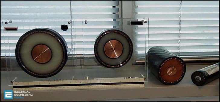
Solid Cable, Cross-Linked Polyethylene
The cross-linked polyethylene (XLPE) underground transmission line is often called solid dielectric cable. The solid dielectric material replaces the pressurized liquid or gas of the pipe-type cables. XLPE cable has become the national standard for underground electric transmission lines less than 200 kV.

There is less maintenance with the solid cable, but impending insulation failures are much more difficult to monitor and detect. The diameter of the XLPE cables increase with voltage. Each transmission line requires three separate cables, similar to the three conductors required for aboveground transmission lines. They are not housed together in a pipe, but are set in concrete ducts or buried side-by-side. Each cable consists of a copper or aluminum conductor and a semi-conducting shield at its core.
A cross-linked polyethylene insulation surrounds the core. The outer covering of the cable consists of a metallic sheath and a plastic jacket.
For 345 kV XLPE construction, two sets of three cables (six cables) are necessary for a number of reasons, primarily so that the capacity of the underground system matches the capacity of the overhead line. This design aids in limiting the scope of any cable failure and shortens restoration time in an emergency situation.
Most underground transmission requires increased down time for the repair of operating problems or maintenance issues compared to overhead lines. The double sets of cables allows for the rerouting of the power through the backup cable set, reducing the down time but increases the construction footprint of the line.
Related electrical guides & articles


Bipul Raman
Bipul Raman (@BipulRaman) is a Technology Enthusiast, Programmer and Blogger. Read more at : https://www.bipul.inProfile: Bipul Raman

You are proving very good and relevant information….
Thank you so much to share this informative article. You have shared lots of information about the electric transmission cable. This article is understandable and increases knowledge.
Is there a problem with induced ac interference with underground cables in metal conduit or jacket sharing ROW with a pipeline. 34.5 kV 5.5 MW ac to 22MW ac?
Thanks,
Tom
For 3.3kV my existing cable was single core 240sq.mm PILC it was failed. no spare cable available. May I replace with 3 core 185sq.mm PVC cable ?
Best
I am doing a exhibit in my community about the movement of energy for kids in my classroom. Is there a way to obtain a sample sectional piece of one of these large XLPE HV cables for display?
thanks!
miles
I have cu/xlpe/pvc 12/20kV mv cables. According to your article, I can use this as my underground rmu supply even its not armored cable or swa. Please confirm as I will proceed with this in my time constraint project. Many thanks