Substation construction planning
All actions involving substation construction require heavy planning. This is especially true of a program of substation uprating or expansion. The trend is toward the assessment of existing substations and individual equipment to develop a predictive maintenance and substation life extension program. There are many figures that need to be carefully planned.

This approach implements a planned program for evaluating substation components and making modifications or individual equipment replacements to improve reliability and extend the overall substation life. Such a program can be operated in conjunction with uprating or expansion planning to optimize the replacement and maintenance of substation equipment.
For instance, major substation uprating or expansion planning might include the replacement of existing outdated protection relays with modern microprocessor relays for improved substation protection and monitoring.
Maintenance planning should be a part of the early stages of uprating or expansion projects. Such planning includes visual inspections, periodic testing, maintaining spare parts inventories, logging of equipment test results, and logging of misoperations and maintenance records.
The Cost
New vs. Uprating or Expansion Existing Substation
Cost is usually a primary factor when determining a course of action: construction of a new facility versus uprating and/or expanding an existing facility. Prepare construction cost estimates for the schemes under consideration.
Generally speaking, substation designers should choose the plan with the most favorable cost/benefit ratio, provided that such action is consistent with the near- and long-range system plan. With facility expansion or new construction, designers should include in cost estimates potential impacts due to underground obstructions and environmental concerns.
During the initial planning of an uprating program, it may become apparent, after discussions with manufacturers, that such a program is not cost-effective. In this case, expansion or new construction is usually the most desirable course of action.
1. Substation uprating
In uprating substation equipment, the cooperation of the equipment manufacturer is usually required. Although an agent or distributor for the equipment vendor may initially be contacted, obtain final determinations from the manufacturer’s headquarters engineering staff as to technical feasibility of the uprating, the cost of such work, and where the work can be done – field or manufacturing plant.
It may be necessary for the work to be performed at the manufacturer’s facilities or by its field service personnel to obtain a proper warranty of the uprated equipment.
When equipment uprating is being considered, only the capacity is increased. The voltage level remains the same. Normally the location of incoming or outgoing circuits remains the same although they may be reconductored for increased capacity.
Go back to the Contents Table ↑
1.1 Major Equipment Uprating
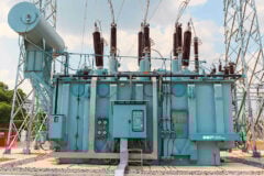
1.1.1 Power Transformer
In the initial phase of a planned substation uprating, furnish the power transformer manufacturer with complete nameplate data. Additionally, supply original purchase information, such as purchase order number and date. This information will make it possible for the manufacturer to retrieve the original design calculations to determine the possible additional capacity.
Insulating oil pumping, or additional pumping, may be necessary to further increase the rating. In some cases, internal leads may require inspection, testing, and even replacement. There are variations between manufacturers but, in general, a 15 to 20 percent increase in MVA capacity may be possible.
Figure 1 – Power transformer


Go back to the Contents Table ↑
1.1.2 Oil Circuit Breaker
Increasing the MVA capacity of a substation may necessitate increased circuit breaker ratings. Breakers may be inadequately rated for increased continuous and momentary currents and interrupting duty. Consequently, determine the fault and continuous current requirements of all associated breakers.
New contacts and bushings may possibly overcome any full load current deficiency. Replacement of interrupter units could safely handle the increased interrupting duty.
The application of capacitors on a substation bus causes severe capacitive current switching duty. Compare rated capacitive switching current for the existing breakers with the anticipated duty to determine the need for breaker mechanism modifications. Consult the breaker manufacturer to determine the need for such modifications.
Figure 2 – 33Kv Oil circuit breaker


Go back to the Contents Table ↑
1.1.3 Current Transformer (CT)
Current transformers should be evaluated for thermal rating under the uprating program by the equipment manufacturer when the apparatus is being assessed. If determined inadequate, a replacement will be necessary. Next, determine the ratio suitability.
For example, a 3000/5 multi-ratio CT, being operated on the 1200/5 tap, can be reconnected for a 2000/5 service. Application of multi-ratio CTs on lower-rated taps results in less accuracy and can lead to saturation of the CTs (with associated error) under heavy fault conditions.
Consider these features in the CT evaluation when fault currents are increased.
Figure 3 – Uprating current transformers (CTs)


Go back to the Contents Table ↑
1.1.4 Wave Trap
Since a wave trap or line trap is a current-rated device, it is undesirable to operate such equipment above the nameplate rating. In most cases of uprating, wave traps will require replacement.
Figure 4 – Uprating a Wave trap


Go back to the Contents Table ↑
1.1.5 Coupling Capacitor Voltage Transformer (CCVT)
A CCVT is a voltage-rated device as is the associated line coupling tuner when the CCVT is equipped with carrier current accessories. Replacement will not be required for a capacity uprating program unless the addition of new metering or relaying exceeds the loading limits of the device.
Note that a voltage transformer (VT) is in the same category as a CCVT relative to uprating.
Membership Upgrade Required
This content is not available in your premium membership plan. Please upgrade your plan in order to access this content. You can choose an annually based Basic, Pro, or Enterprise membership plan. Subscribe and enjoy studying specialized technical articles, online video courses, electrical engineering guides, and papers.
With EEP’s premium membership, you get additional essence that enhances your knowledge and experience in low- medium- and high-voltage engineering fields.
Black Friday Deal 💥 – Save 20% on Pro Plan with code BLACKFRIDAY
Copyright Notice
This technical article is protected by U.S. and international copyright laws. Reproduction and distribution of PDF version of this technical article to websites such as Linkedin, Scribd, Facebook and others without written permission of the sponsor is illegal and strictly prohibited.© EEP-Electrical Engineering Portal.
Related electrical guides & articles
Premium Membership
Edvard Csanyi
Hi, I'm an electrical engineer, programmer and founder of EEP - Electrical Engineering Portal. I worked twelve years at Schneider Electric in the position of technical support for low- and medium-voltage projects and the design of busbar trunking systems.I'm highly specialized in the design of LV/MV switchgear and low-voltage, high-power busbar trunking (<6300A) in substations, commercial buildings and industry facilities. I'm also a professional in AutoCAD programming.
Profile: Edvard Csanyi

