
Estimated Study Time: 14 minutes
Saving in investment and operating costs
This technical analysis was carried out by ABB to show that for urban supply networks the combination of HV gas insulated switchgear – GIS (due to their compactness and flexibility) and HV cable has important advantages over systems with air insulated switchgear – AIS and overhead lines.
 What would be the best solution for urban supply networks - AIS or GIS systems? (on photo: ABB Ireland delivers the largest 110 kV GIS with the greatest number of ELK-04 units in Europe; credit: ABB)
At least, this study shows this result.
Besides the vital role they play in modern market economies, electricity supply systems also have a large impact on the environment, making them subject to changes in social paradigms. It is in part due to this that the medium voltage systems supplying power to urban areas are designed today almost entirely as cable networks with indoor switching stations.
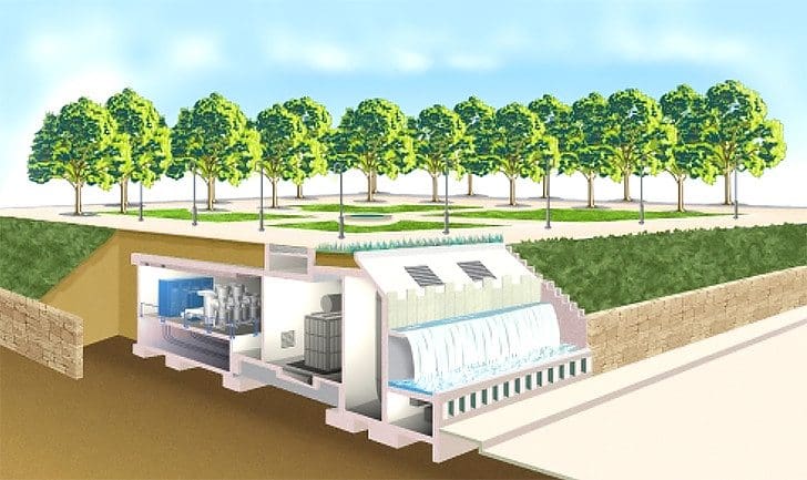
Besides its reduced visual ‘intrusion’ on everyday life, gas insulated switchgear (GIS) also offers operators of high voltage supply systems reliable and flexible solutions in areas where load densities are high and substation sites have to be kept small.
Urban supply systems combining GIS technology and HV cable are safe, reliable and environmentally benign (Figure 1) .
A direct comparison of the component investment for identical switchgear configurations suggests that the GIS variant is more costly than the air insulated switchgear (AIS) solution.
However, such a comparison does not take into account the fact that by locating a GIS transformer substation close to the load centers a far more efficient network structure is obtained at both the HV and the MV distribution level. As a result, the investment and operating costs are reduced.
To quantify the respective impact of AIS and GIS technology at the HV and the MV levels of an urban supply system, a look is taken in the following at an existing network with a maximum load of 120 MW. The MV network is optimized for each of the HV variants (GIS and AIS), in each case for distribution voltages of 10 kV and 20 kV, so that four different HV/MV networks are evaluated.
The comparison is based on the life-cycle costs of the different supply concepts.
Design of the AIS and GIS network variants
A. High voltage network
The best locations for the HV injections into the distribution network depend to a large extent on the technology (AIS or GIS) chosen for the HV system. Sites which are large enough for AIS substations are seldom available, and when they are their cost is extremely high.
But it is not just the smaller size of the site that makes GIS the lower-cost option! GIS is also the more economic alternative when expanding or replacing existing substations. An inner-city site that has been used previously for an AIS installation can be sold or rented out and the income used to help finance the new substation.
The issue of space extends beyond the transformer substations to the high voltage connections. Overhead lines are today practically ‘no-go’ as an option for inner-city areas. And even where rights-of-way are available, these can often be utilized more economically in other ways.
Typical complaints about overhead lines are that they are unsightly and generate electromagnetic fields, the effects of which are subject to constant and intensive public debate.

Modern-day HV cable not only offers a high level of reliability, but also some technical benefits for overhead line connections. Given these advantages, there is today no realistic alternative to HV cables for electric supplies in urban areas.
Go back to Design of the AIS/GIS network variants ↑
GIS – Gas Insulated Switchgear
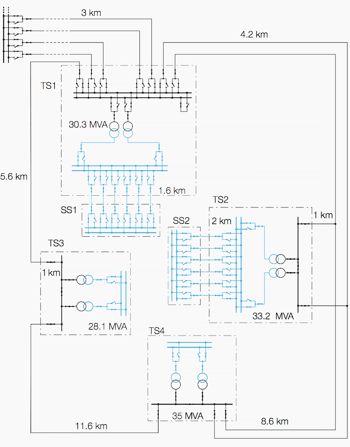
The GIS variant 2 considered in the study consists of three HV transformer substations located in the center of a city. The connection to the surrounding 110 kV network is provided by three cables run from the nearest HV substation to the main substation of the urban HV network.

This main substation is configured as a double busbar system, allowing maintenance to be carried out on one busbar without having to de-energize the complete station. The remaining substations in the HV cable ring, which are also located in the city center, are H-type transformer substations with a bus-tie.
They also allow maintenance and repairs within the gas compartment on one half of the busbar while the other half remains in operation.
Go back to Design of the AIS/GIS network variants ↑
AIS – Air Insulated Switchgear
In the AIS variant 3 there is an overhead line loop around the supply region, the right half of which consists of double lines (due to the load flows).
As in the GIS variant, the main HV substation consists of a double busbar system, the remaining HV transformer substations having H-type configurations. Transformer substation TS2 has a double-T connection to the double overhead line, substation TS3 being looped into the single line on the left-hand side.
Due to the larger space required, the transformer substations are located in the less densely populated outer regions of the city.
Double lines connect the outer ring to the transformer substations, ie there are two circuits on the same poles. This solution allows efficient utilization of the available space.
However, it also reduces the reliability of the HV supply as both circuits can trip for the same reason (‘common mode failure’, eg due to back-flashover from the earth wire to both circuits caused by lightning striking the earth wire or contact with trees).
Go back to Design of the AIS/GIS network variants ↑
B. Medium voltage network
A comparison of the GIS and the AIS variants based only on the differences in the HV network is too limited, since the locations of the HV transformer substations are of decisive importance and exert a large influence on the structure of the MV network.
The study therefore takes the load situation in an actual urban network, including the load values and the geographical location of the MV transformer substations, as its starting point (Figure 4 below).
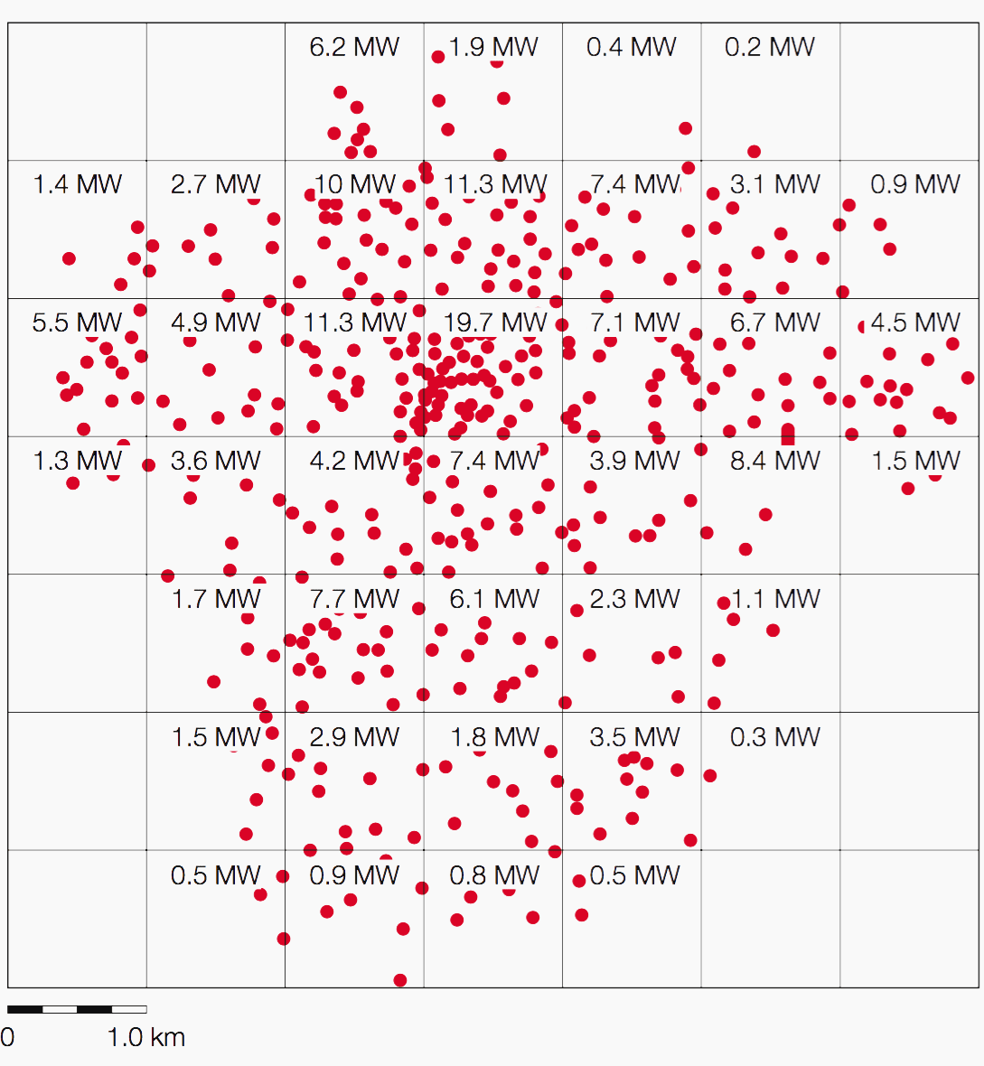
Radial operation of an MV network results in a large number of possible network concepts. Besides differing in terms of their initial capital costs, they also considerably influence operation of the network.
Go back to Design of the AIS/GIS network variants ↑
Planning rules
The technical constraints for each network variant are the allowed voltage band and the limits for the short-circuit power, which are dictated by the rating of the switchgear. There are also some design rules to be formulated:
Use of standard components:
- XLPE MV cables with an Al cross-section of 150 mm2 (distribution cables) and 240 mm2 (transmission cables)
- 110 kV/MV transformers with a rated power of 31.5/40 MVA
Open-loop topology for the distribution network
The distribution cables start from the MV busbar of the HV/MV transformer substations, run between customers’ substations and are looped back to the MV busbar of the same HV transformer substation. During normal operation one of the cables in this ring remains open to provide simple protection.
Maximum of 14 customer substations in a loop
This limits the number of customers whose power supply would be interrupted in the event of an MV network failure, as only the feeder connected to the HV/MV station busbar is equipped with overcurrent protection and a circuit breaker.
Normal loading of the feeder cables
So that a worst-case cable failure (feeder failure close to the HV/MV transformer substation) does not load any cable beyond 120% of its capacity. The maximum load of 5.2 MVA per cable at 10 kV (10.2 MVA at 20 kV) at the beginning of the planning period takes into account the reduced ampacity for cables bundled in the same cable trench close to the transformer as well as a margin for load growth during the planning period.
Go back to Design of the AIS/GIS network variants ↑
Planning results
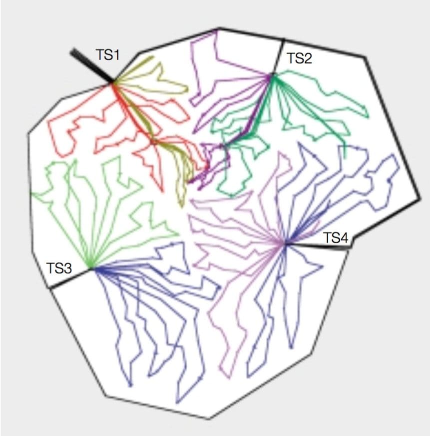
The inherent flexibility of GIS allows planners to place the injection points close to the load centers (see Figure 5). The first effect of this is on the number of loads considered an optimum for each HV substation, and thus on its installed transformer capacity.
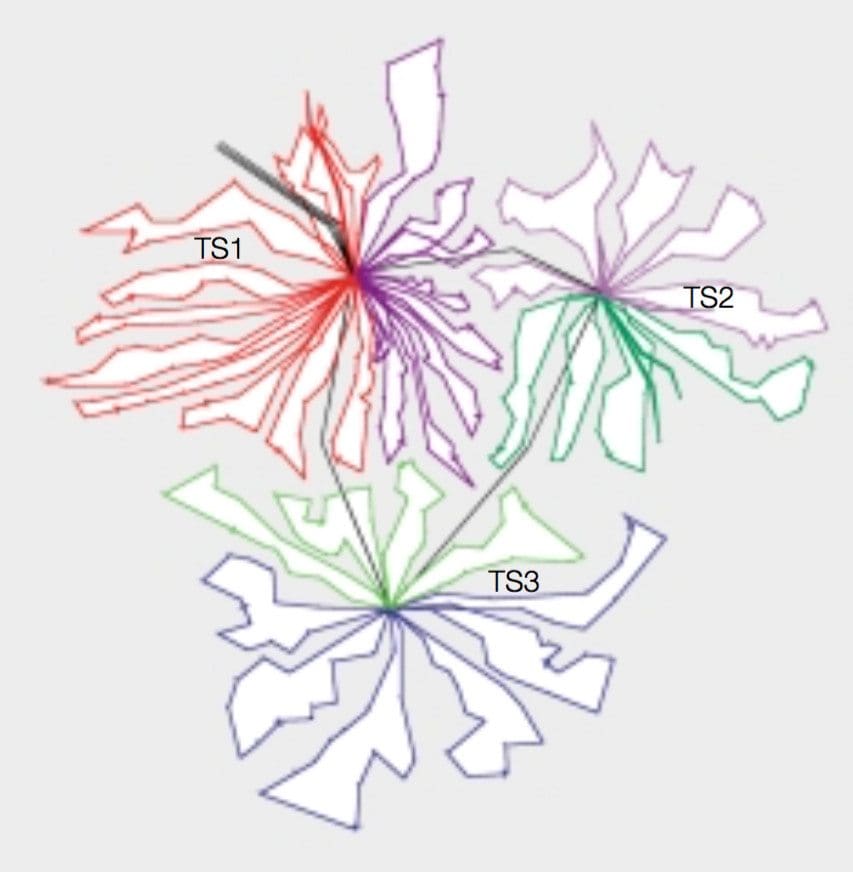
Secondly, it reduces the required power transmission capability of the MV network, allowing an additional saving due to the smaller MV cable cross-sections required. And thirdly, transmission losses are avoided. The reduction in operating costs due to this third advantage is especially evident at low distribution voltages.
The peripheral locations of the transformer substations in the AIS variant make additional satellite stations necessary (see Figure 6).
These have remote MV busbars, fed by the HV transformer substations via several parallel and selectively protected transmission cables. Their reliability is comparable with the reliability of the MV busbar of the HV transformer substations, but they call for extra capital investment and cause additional losses.
The AIS variant with a voltage of 10 kV requires 6 parallel cables from the HV injection to the satellite station, the 20 kV variant requiring 4 cables. These satellite busbars, like the MV busbars of the HV substations, supply power to the MV substations via open loops.
Go back to Design of the AIS/GIS network variants ↑
Reference // Werner Zimmermann, André Osterholt and Dr. Jürgen Backes (ABB Calor Emag Schaltanlagen AG)
Related electrical guides & articles


Edvard Csanyi
Hi, I'm an electrical engineer, programmer and founder of EEP - Electrical Engineering Portal. I worked twelve years at Schneider Electric in the position of technical support for low- and medium-voltage projects and the design of busbar trunking systems.I'm highly specialized in the design of LV/MV switchgear and low-voltage, high-power busbar trunking (<6300A) in substations, commercial buildings and industry facilities. I'm also a professional in AutoCAD programming.
Profile: Edvard Csanyi

Dear Mr.Edward,
Greetings.
You doing extremely great job by providing the very needful information for electrical engineers. Please, clear me one clarification. Is that in transformers say 132/33kV, 3 phase traansformer, what is the purpose of territory winding? Why it is required?
Please, clarify. Waiting for your valuable information.
Thanks and regards.
Yours Sincerely,
J.VISVESVARA RAO
thanks a lot Edvard. this is a good article. we translate some of your articles in persian with link of your website as reference.