
Estimated Study Time: 11 minutes
Interconnection schemes
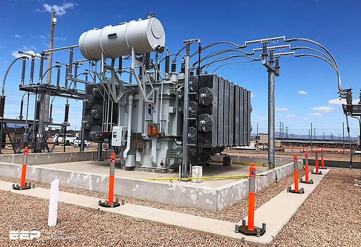
The utility-consumer interconnection provides the path for power flow between supplier (utility) and user (consumer). The interconnection may comprise one or more circuits and is assumed to include voltage transformation.
 Typical utility-consumer interconnection configurations
For the purposes of this guide, the interconnection extends from the nearest source-side protective device used for switching on the transformer high-voltage side to the transformer low-side bus and switching devices.
The consumer load requirements will strongly influence the degree to which each of these aspects is considered. This technical article illustrates few most common arrangements with note that numerous other service arrangements are in general use.
- Single supply-single transformer
- Transformer with high-side fuse
- Transformer with high-side breaker
- Transformer with high-side breaker and bypass switches
- Dual supply-single transformer
- Manually-operated load-break switches
- Motor-operated load-break switches
- Circuit breakers
- Dual supply-dual transformer
- Single-supply circuit breakers
- Multiple-supply circuit breakers
- Ring bus configuration
1. Single supply-single transformer
This is a common form of utility-consumer interconnection. It consists of a single transformer connected to a single source. The consumer will generally have multiple feeders connected to the low-voltage side of the transformer.
Supply from this configuration is subject to interruption upon loss of the supply source, line, or transformer.
Figure 1 is a basic single supply-single transformer interconnection.
A consumer power outage will be necessary if maintenance is required on any of the system components other than the consumer feeder devices.

In Figure 2, the fused-disconnect switch has been replaced with a circuit breaker. Protective relays, measuring high-side current, can now be utilized to provide additional protection for the transformer and low-voltage bus.
Again, the consumer is subject to an outage when maintenance is required.
The system design of Figure 3 allows the interconnection circuit breaker to be removed from service for maintenance without a consumer outage, although additional protective relaying will be required at the utility source to maintain acceptable transformer protection.
A maintenance outage of the supply line or transformer will still cause a consumer outage.
2. Dual supply-single transformer
Two or more full capacity supply lines will greatly enhance continuity of service. Because of its extensive exposure, the supply line is generally the least reliable component of the utility-consumer interconnection.
A dual supply allows dead line maintenance to be performed without an interruption to the consumer. Figure 4 illustrates a dual supply with two manually operated switches located at the consumer load bus.

System configuration may require the supplies to be looped together (i.e., both switches closed) or operated as two radial sources with one of the switches open.
a) Looped mode
This mode dictates that both switches be closed during normal operation. A fault anywhere on the supply lines will cause a consumer outage. The switches can be used to isolate the faulted section and restore service to the consumer load bus via the remaining supply line. Outage time may be somewhat lengthy while switching is done to isolate the faulted section.
Looped mode operation generally provides the consumer with a stronger source.
b) Transfer mode
In this mode, one of the switches at the consumer load bus is operated normally open. If a fault occurs on the supply line feeding the consumer, it can be isolated and service restored by closing the normally open switch. It is recommended that the normally open supply line remain energized at all times to ensure the availability of that source.
In Figure 5, motor-operated disconnects are used for switching loads at the consumer bus. This system also may be operated in either the looped or transfer mode.
Sectionalizing systems are available that will automatically isolate a faulted line section and restore consumer load, reducing the outage time.

In Figure 6, the motor-operated disconnect switches are replaced with circuit breakers. Now the consumer is served with two supply lines with separate protective equipment. Note that circuit breaker disconnect switches are provided for maintenance purposes.
Bypasses may also be added if a looped system must be maintained.
3. Dual supply-dual transformer
The addition of a second transformer will also increase reliability. If each transformer is sized to carry total consumer load requirements, plant production need not be affected by the loss of a single transformer.
Figure 7 illustrates a dual supply-dual transformer configuration. Fuses are shown in this example, but replacing the fuse with high-side transformer circuit breakers or circuit switchers, and adding differential relays, will improve transformer protection.
Operating the system shown in Figure 7, with the low-voltage buses isolated from each other, minimizes fault current levels and provides for the isolation of plant equipment. If the low-voltage buses are not isolated but are operated in parallel (i.e., with the low-voltage tie closed and both transformers in service) additional protection is required on the low-voltage, and possibly the high-voltage, side of each transformer.
Voltage transients from feeder or bus faults are less likely to impact total plant operation if the low-voltage buses are normally isolated. This may be particularly advantageous if there is voltage-sensitive equipment.
Maximum short-circuit fault current on the low-voltage system will approximately double if the buses are operated in parallel. This may be an important consideration when choosing interrupting ratings. Operating the buses isolated may allow application of lower rated, and thus less expensive, feeder fuses and circuit breakers.
However, if the feeder equipment is not rated to withstand the short-circuit current for a fault with both buses in parallel, then provisions must be included in the design of the control system to ensure that both main breakers cannot be closed at the same time as the bus-tie breaker.
In this case, the consumer must recognize that outages are required for switching.
Improved transformer protection and service reliability may be obtained with the addition of supply line circuit breakers as shown in Figure 8 below. With this configuration, a supply line fault does not require an outage of a transformer.
Operation with the low-voltage tie closed will provide continuous service to all consumer loads in the event of a transformer fault.
However, as discussed above, careful consideration of plant operation is necessary to determine the normal position of the low-voltage bus-tie breaker.
Bypass switches will be required on the high-voltage supply-side breakers if supply lines A and B are to be looped together at all times. The relay systems should provide adequate protection when the high-voltage breakers are bypassed.

Figure 9 uses a ring bus on the supply side of the interconnection. With this system, transformer faults will not interrupt the remaining feed to the consumer or the connection between supply lines A and B, maintenance may be performed on any of the supply-side breakers without the use of bypass switches, and the failure of a single breaker will not interrupt the total electric supply.
Service reliability to the consumer is improved if sources and loads are alternately connected around the ring bus. The low-side buses may be operated in parallel.
Again, careful consideration should be given to plant requirements to determine the optimum operating position of the low-side bus-tie breaker.

References // IEEE Std C37.95 – IEEE Guide for Protective Relaying of Utility-Consumer Interconnections
Related electrical guides & articles


Edvard Csanyi
Hi, I'm an electrical engineer, programmer and founder of EEP - Electrical Engineering Portal. I worked twelve years at Schneider Electric in the position of technical support for low- and medium-voltage projects and the design of busbar trunking systems.I'm highly specialized in the design of LV/MV switchgear and low-voltage, high-power busbar trunking (<6300A) in substations, commercial buildings and industry facilities. I'm also a professional in AutoCAD programming.
Profile: Edvard Csanyi

dears, your website can be considered the references for the Electrical designers, let the readers copy the text and past in their reports