
Estimated Study Time: 40 minutes
Troubleshooting VFDs
Proper analysis of the VFD’s power and control circuit diagrams is essential for successful troubleshooting. But before starting any analysis, you must know how your system connected through VFD works and how it breathes. You must also know all components of your variable frequency drive panel. A real-world example of VFD power and control circuit diagrams for smoke extraction fan will be analyzed.
 Inside Variable Frequency Drive (VFD) panel: Configuration, schematics and troubleshooting
The article starts with the essential basics, VFD parameters and their configuration, interfacing, and slowly moves to the detailed troubleshooting steps. As you will learn from this article, there are many steps that need to be taken into account to complete troubleshooting task successfully and avoid any failures.
The article is dedicated to both novice electrical engineers and senior engineers involved in motor control and maintenance.
- Introduction to VFDs
- Block Diagram of VFD
- VFD Parameters
- Configuration of Parameters
- Control Circuit
- BMS Interfacing
- Fire Alarm Interfacing
- Troubleshooting VFDs
1. Introduction to VFDs
For many years, the major challenge to some motor-driven applications was the inability to control their speed. However, the advent of reliable power electronics made it possible to control the speed of motors using variable-frequency drivers.
VFDs are widely used in many applications nowadays. The main reason is that they have greater functionality and operation capabilities compared to conventional motor drives when starting a motor.
In this article, we will discuss VFD working principle, applications, configuration, construction diagrams, interfaces with other systems, and troubleshooting.
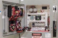
Figure 1 – Variable Frequency Drive (VFD)

Go back to the Contents Table ↑
2. Block Diagram of VFD
To understand the working principle of a variable frequency driver, it is important to know what it is composed of. In other words, you need to know what leads the currents passing through a VFD of a 3-phase motor, for instance, to be changed from AC to DC and then back to AC again.
VFD comprises three main sections: Rectifier, Filters, and Inverter.
- Rectifier: The first stage of VFD. It converts AC power fed from the mains to DC power. It mainly utilizes diodes that are connected in parallel to convert AC power into DC.
- Filter: A capacitor that is used to smooth the rectified DC power.
- Inverter: Transistors (IGBTs) used to work to be switched on and off rapidly to create a pulse-width modulation which creates an AC-like wave that will allow the VFD to control the speed of the motor.
The following diagram shows the circuit diagram of a variable frequency drive (VFD).
Figure 2 – VFD Circuit Diagram

Go back to the Contents Table ↑
2.1. Working Principle
It is important to be familiar with the working principle of VFDs as they are extensively used in AC motor-driven applications. VFD has greater functionality and operation capabilities than conventional motor drives, which will be explained in detail in this article.
Let’s take a 3-phase load as an example to see how VFDs work. Firstly, when AC power is supplied from the mains, it directly passes through the first VFD stage – Rectifier stage. The current passes through six diodes that convert the AC-supplied current into DC. In short, each of the three phases is connected to one pair of diodes, which only allow the peak of each phase to pass through it.
Therefore, the output of the 3 phases passing through diodes, when measured by an oscilloscope, will look like the following graph:
Figure 3 – Rectifier Output Current Wave

Suggested Video – Output Voltage/Current Waveforms for a VFD
This video shows what the output voltage and output current waveforms will look like when a 3HP VFD is powered, and there are no filter products between the VFD and the motor. The VFD cable length between the VFD and the motor is 500 ft.
As you can see the output current looks like a rough DC or just a current wave that doesn’t include the negative side of the current. Therefore, this current needs to be converted into a healthy DC and the best way to achieve that is by connecting a capacitor that will smooth the output current.
This capacitor is the VFD’s second stage, called the DC filter. Because of the charging and discharging effect of the capacitor, the current passing through the DC filter will have a wave, as shown in Figure 4.
The IGBTs here act like switches that when rapidly switched on and off, create the Pulse-Width Modulation (PWM) that is a key to allowing a VFD to control the speed of the motor.
Figure 4 – Effect of a Capacitor on a Rectified Signal
This concept of rapid PWM transistor switching allows the drive to carve any arbitrary waveform out of the filtered DC voltage it receives from the rectifier. Virtually any frequency may be synthesized (up to a maximum limited by the frequency of the PWM pulsing) giving the VFD the ability to power an induction motor over a wide range of speeds.
The conversion of DC into AC is depicted in the graph below as a pure sinewave. As we can see, the wave is somewhat squared. Not all applications often experience this wave. We may adjust the waveform by entering particular parameters into the VFD controller.
The VFD controller will then adjust the frequency by further adjusting the timing of the switches to set a frequency corresponding to the connected motor’s speed.
Figure 5 – Output of VFD Wave

Go back to the Contents Table ↑
3. VFD Parameters
After we have reminded ourselves how VFDs work by looking at their waveform when the current passes, we will start looking at the practical side of it, which is more critical for installation, configuration, and troubleshooting on-site.
For a VFD to properly and safely control an electric motor, the drive must ‘know’ specific data about the connected electric motor and its intended application. AC motors have voltage, current, frequency power ratings, etc. These ratings are typically found on a metal nameplate affixed to a motor frame where they can be easily read.
Related electrical guides & articles


Mohammed Ayman
I earned my degree from Eastern Mediterranean University (Turkey, North Cyprus) in B.S Electrical & Electronic Engineering; shortly after, I began my career as an electrical site engineer in a mega-scale project in Qatar which allowed me to monitor and supervise electrical site installations. I indulged in the design field of the electrical low voltage distribution systems and have accomplished more than 10 projects with the compliance of the national codes & international standards.Profile: Mohammed Ayman
