
Voltage drop considerations
The first consideration for voltage drop is that under the steady-state conditions of normal load, the voltage at the utilization equipment must be adequate.
 Voltage drop calculation methods with examples explained in details
In addition to steady-state conditions, voltage drop under transient conditions, with sudden high-current, short-time loads, must be considered.
The most common loads of this type are motor inrush currents during starting. These loads cause a voltage dip on the system as a result of the voltage drop in conductors, transformers and generators under the high current. This voltage dip can have numerous adverse effects on equipment in the system, and equipment and conductors must be designed and sized to minimize these problems.
In many cases, reduced-voltage starting of motors to reduce inrush current will be necessary.
Voltage drop formulas
Let’s see two most common methods for calculation of voltage drop – approximate and exact methods:
1. Approximate method
Voltage drop EVD = IR cosθ + IX sinθ where abbreviations are same as below “Exact Method”.
2. Exact method #1
If sending end voltage and load PF are known.
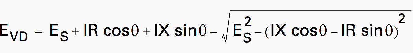
where:
- EVD – Voltage drop, line-to-neutral, volts
- Es – Source voltage, line-to-neutral, volts
- I – Line (Load) current, amperes
- R – Circuit (branch, feeder) resistance, ohms
- X – Circuit (branch, feeder) reactance, ohms
- cosθ – Power factor of load, decimal
- sinθ – Reactive factor of load, decimal
If the receiving end voltage, load current and power factor (PF) are known.
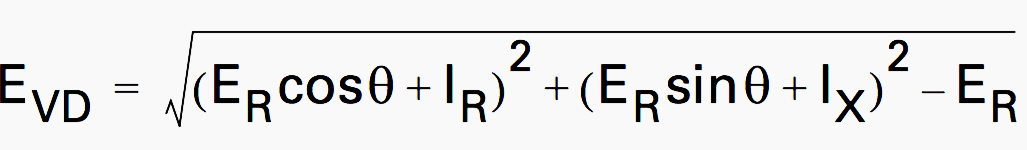
ER is the receiving end voltage.
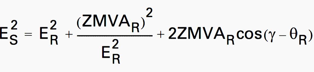
2. Exact Method #2
If receiving or sending mVA and its power factor are known at a known sending or receiving voltage.
or
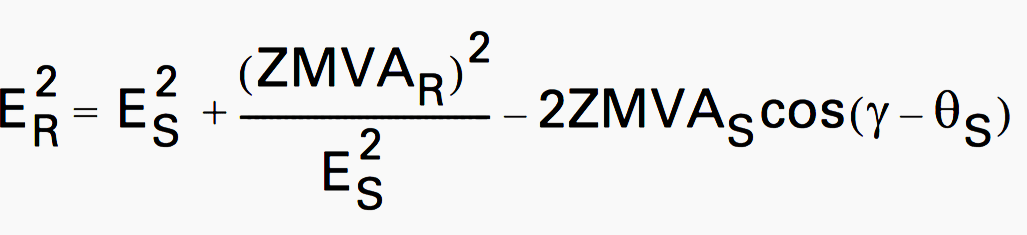
where:
- ER – Receiving line-line voltage in kV
- ES – Sending line-line voltage in kV
- MVAR – Receiving three-phase mVA
- MVAS – Sending three-phase mVA
- Z – Impedance between and receiving ends
- γ – The angle of impedance Z
- R – Receiving end PF
- S – Sending end PF, positive when lagging
Voltage drop tables
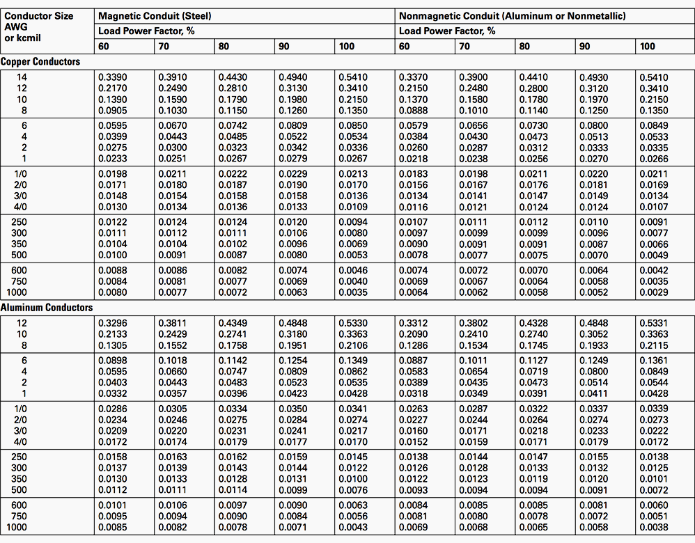
Tables for calculating voltage drop for copper and aluminum conductors, in either magnetic (steel) or nonmagnetic (aluminum or non-metallic) conduit, are shown below. These tables give voltage drop per ampere per 100 ft (30 m) of circuit length.
The circuit length is from the beginning point to the end point of the circuit regardless of the number of conductors.
Tables are based on the following conditions:
Condition #1
Three or four single conductors in a conduit, random lay. For three-conductor cable, actual voltage drop will be approximately the same for small conductor sizes and high power factors. Actual voltage drop will be from 10 to 15% lower for larger conductor sizes and lower power factors.
Condition #2
Voltage drops are phase-to-phase, for three-phase, three-wire or three-phase, four-wire 60 Hz circuits. For other circuits, multiply voltage drop given in the tables by the following correction factors:
Correction factors table:
| Three-phase, four-wire, phase-to-neutral | × 0.577 |
| Single-phase, two-wire | × 1.155 |
| Single-phase, three-wire, phase-to-phase | × 1.155 |
| Single-phase, three-wire, phase-to-neutral | × 0.577 |
Condition #3
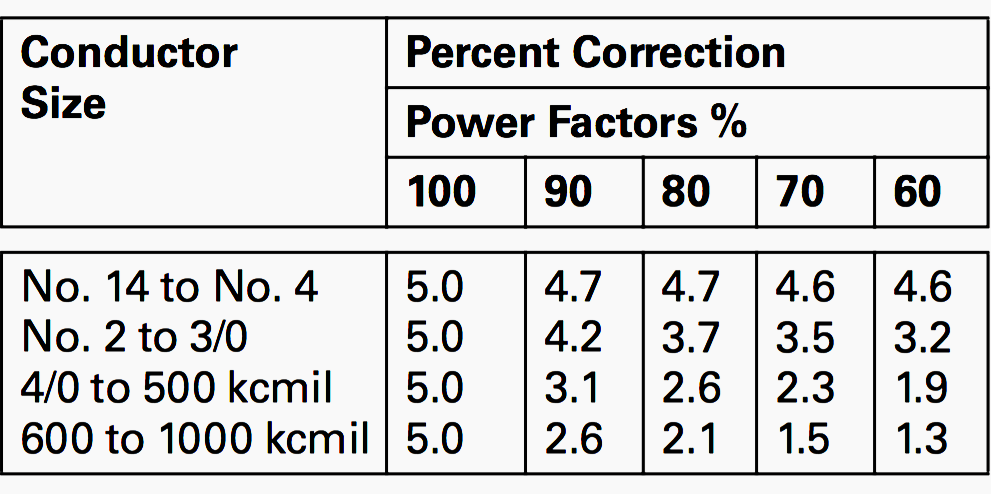
Voltage drops are for a conductor temperature of 75 °C. They may be used for conductor temperatures between 60 °C and 90 °C with reasonable accuracy (within ±5%). However, correction factors in Table 1 can be applied if desired. The values in the table are in percent of total voltage drop.
- For conductor temperature of 60 °C – SUBTRACT the percentage from Table 1.
- For conductor temperature of 90 °C – ADD the percentage from Table 1.
Calculations
To calculate voltage drop:
- Multiply current in amperes by the length of the circuit in feet to get ampere-feet. Circuit length is the distance from the point of origin to the load end of the circuit.
- Divide by 100.
- Multiply by proper voltage drop value in tables. Result is voltage drop.
Example #1
A 460 V, 100 hp motor, running at 80% PF, draws 124 A full-load current. It is fed by three 2/0 copper conductors in steel conduit. The feeder length is 150 ft (46 m).
- 124 A × 150ft (46m) = 18,600 A-ft
- Divided by 100 = 186
- Table: 2/0 copper, magnetic conduit,
80% PF = 0.0187
186 x 0.0187 = 3.48 V drop
3.48/460 x 100 = 0.76% drop
Conclusion: 0.76% voltage drop is very acceptable. (See NEC Article 215, which suggests that a voltage drop of 3% or less on a feeder is acceptable.)
To select minimum conductor size:
- Determine maximum desired i voltage drop, in volts.
- Divide voltage drop by ii (amperes x circuit feet).
- Multiply by 100.
- Find nearest lower voltage drop value in tables, in correct column for type of conductor, conduit and power factor. Read conductor size for that value.
- Where this results in an oversized cable, verify cable lug sizes for molded case circuit breakers and fusible 4 switches. Where lug size available is exceeded, go to next higher rating.
Example #2
A three-phase, four-wire lighting feeder on a 208 V circuit is 250 ft (76.2 m) long. The load is 175 A at 90% PF. It is desired to use aluminum 7 conductors in aluminum conduit.
- VD = 2/100 × 208 = 4.16 V
- 4.16 / (175 × 250) = 0.0000951
- 0.0000951 × 100= 0.00951
- In table, under aluminum conductors, nonmagnetic conduit, 90% PF, the nearest lower value is 0.0091. Conductor required is 12 500 kcmil.
(Size 4/0 THW would have adequate ampacity, but the voltage drop would be excessive.)
Table 2 – Voltage Drop—Volts per Ampere per 100 Feet (30 m); Three-Phase, Phase-to-Phase
Reference // Power Distribution Systems by EATON


We are building a solar PV park 4.1 MW/120ams the distance to the substation is 20Km with 70mm2(2/0 awg) grid connection cable. Grid Voltage is 22KV We calculate voltage drop 5%. You believe this acceptable or We will have problems with the PV park operation?
Thank you!
I’m somewhat confused about the voltage drop tables, particularly the relationship between voltage drop and a load’s power factor. If I recall correctly, higher power factor loads should result in lower voltage drops, and vice versa. However, some tables seem to show the opposite: that higher power factor loads lead to higher voltage drops. Could you please explain this discrepancy for me?
hi ive been asked to calculate cable size for an ac rectified by ups pv cells array for my brothers home in France. The ups/controller might not exactly put out a sinewave. the outout might be 25 kW distance to house from array maximum might be 100metres in ground. can you describe the calculation and method to be used please i reckon on it being 100A and about 10.5VD. his cottage has very thick stone walls fitted with some insulation, what – god only knows, its a 17th century cottage in Brittany the onky reason he hasnt got PV on his cottage roof and must take it off the top of his green house is because it is thatched. the greenhouse is ineffective as hes used thick plexiglass for the wall in fills the roof is vinyl and felt. and he uses maybe 6 large panels and two controllers to each set of two lorry batteries. I would say 3 core, for the earth, 25 to 32mm swa xple lsf cable. What is your recommendation please.
regards Frank ex power station tech and MIET member.
What is the voltage drop on a 2000ft run of #2 use direct burial at 240vac 20 amp max load
DC Circuit. 12vdc
example: I’m installing a 1000w pure sine inverter in the back of the box of my truck. Length from truck battery to load connection of the inverter is approximately 15 feet.
When you increase the wire size for voltage drop for a load current of 12 amps, must you physically keep that same size of wire connected from source to the load connection of the inverter?( with no interruption of wire size) There is a relay just after the truck battery, then continues to the inverter. But it’s difficult to physically put a # 8 gauge copper wire on the 30 amp. rated relay. They don’t make a #8 gauge female stak-on crimp connector.
The question is: can I go down to a # 10 Gauge copper wire to make the connection to the relay, from # 8 gauge to # 10 gauge on both sides of the relay then back up to # 8 gauge travelling to the inverter without increasing the voltage drop?
Thank you
Reducing the cable size for a short distance will have minimal effect on voltage drop. It’s a function of cable impedance only. But, your numbers don’t make sense.
1000W/24Vdc = 42A. You stated it was a 12A load.
Please I need the analysis for voltage rise.
Im confused with correction factor table in condition #2. Should this item be “Three-phase, three wire, phase-to-phase x1.155” instead of “Single-phase, three wire, phase-to-phase x1.155”
IHAVE AN LANDSCAPING LED LIGHTS 30NOS CONNECTED IN SERIES FOR ADISTANCE OF 380METERS ZIGZAG LINE .
HOW IWILL GET THE CABLE SIZE AND HOW TO ELEIMENATE VOLTAGE DROP
PLEASE ANSWER ME AS SOON AS POSSIBLE.
BEST REGARDS
If found it stranges how dificult it seem to calculate pressure drop.
The resistance in conductors = Lengh x 0,0175/Divide by Cross sectional area.
The voltage drop 20 meter conduct , 10 Ampere ,1,5mm2, =4,7 Volt. That is for 2 wire cable
ٍER, Must be outside the radical
Hi,
How do you compute the voltage drop of a feeder installed in cable tray? Considering also the ambient temperature. I want to reduce cost by proper selection of cable size and number of set considering the voltage drop of main feeder cable.
i wont voltage drop 70sqmm 3 cor HV cable.( 600m lenght)..
voltage start from stepup transformer 11,000kv.
600m end is my other resort.
In a previous example:
124 x 154ft ÷ 100 = 186 x 0.0187 = 3.48drop
I need to clarify that in a 3-phase system you have to multiply it by 1.732
Vd = 1.732 x Amp x Length x R / 100f
Dear Edvard Csanyi;
Kindly advise me if the Demand factor should be used for the calculation of Voltage drop or not? Kindly submit the formula if the demand factor should be used.
NO Response!!!!!!!!!!!!!!!!!!!!!!!!
Is there any change in voltage drop calculation if the cable is armoured and if so let us know the correction to be applied
pls send sample computation for volatage drop and short circuit using per unit method
I Want Voltage Drop Calculation For Single Phase System (Solar). Please share
Nice to know this. Bit can we get a link to download all these calculations for better understanding and to teach others.
Dear Edvard:
Please Show The Mathematical Derive Of The Equation Of Exact Method #1 (And How Sending End Voltage (Vs) Appears In Voltage Drop Formula .
Best Regards ,
Hi everybody,
In fact I have a confussion for which power factor I use in determining voltage drop of main cable (30m length) which supplies two motors (1st one 50HP , o.85 p.f, with 100m cable) and (2nd one 100HP , o.75 p.f,with 300m cable) .
Your answer is too much appreciated .
Thanks in advance
1- APPLY SUPERPOSITION THEOREM
2- APPLY PHASOR SUMMATION MOY ALGEBRAIC SUMMATION
3- THE MAIN SUPPLY WILL HAVE A DIFFERENT P.F. FROM BOTH
I saw the comments above and I guess what Gerald is referring to is the K factor method which is popularly followed by NEC. However, NEC also supports the IEEE 141-1993 formula. Refer to bottom of Table 9 Note 2 of NEC which clearly says: Multiplying current by effective impedance gives good approximation for line to neutral voltage drop. Thus, the approximate formula (Sqrt(3)*I*(Rcosphi+Xsinphi) can be followed. For all practical purposes, I have used this formula for last 25 years. The exact formula can also be used, and there is a vectorial method to get the solution.
Dear Engineers,
GERALD NEWTON AND TOMMY RICE.
Please tell me your methods of voltage drop calculations I will be grateful for you to let me know the best way of calculation because I am new in this field.
best regards
Eng. Abdolgabar Ahmed
Your voltage drop calculation article is off the wall. Sorry, but this is not how it is done. Furthermore, the State of Washington specifically states in a news letter how the inspectors want the calculation done. I have been in this business for over 40 years and have never, ever seen anything like your method. I suggest you do some research on how practical engineers and electricians do voltage drop calculations.
could you e-mail me and tell me how Washington state wants their calculations done. I use a different method for voltage drop calculations than edvard csanyi