
Estimated Study Time: 5 minutes
Voltage drop formulas
Voltage drop calculations using the DC-resistance formula are not always accurate for AC circuits, especially for those with a less-than-unity power factor or for those that use conductors larger than 2 AWG.
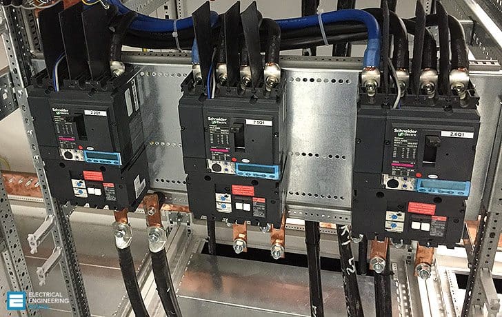 Voltage Drop Calculations For Engineers - Beginners (on photo: Low voltage circuit breakers type NSX 250H, 600V)
Table 1 allows engineers to perform simple ac voltage drop calculations. Table 1 was compiled using the Neher–McGrath ac-resistance calculation method, and the values presented are both reliable and conservative. This table contains completed calculations of effective impedance (Z) for the average ac circuit with an 85 percent power factor (see Calculation Example 1).
The basic assumptions and the limitations of Table 1 are as follows:
- Capacitive reactance is ignored.
- There are three conductors in a raceway.
- The calculated voltage drop values are approximate.
- For circuits with other parameters, the Neher–McGrath ac-resistance calculation method is used.
Calculation Example #1
A feeder has a 100 A continuous load. The system source is 240 volts, 3 phase, and the supplying circuit breaker is 125 A. The feeder is in a trade size 1¼ aluminum conduit with three 1 AWG THHN copper conductors operating at their maximum temperature rating of 75°C. The circuit length is 150 ft, and the power factor is 85 percent.
See the solution //
STEP-1 // Find the approximate line-to-neutral voltage drop.
Using the Table 1 column “Effective Zat 0.85 PF for Uncoated Copper Wires”, select aluminum conduit and size 1 AWG copper wire. Use the given value of 0.16 ohm per 1000 ft in the following formula:
STEP-2 // Find the line-to-line voltage drop:
STEP-3 // Find the voltage present at the load end of the circuit:
![]()
Calculation Example #2
A 270 A continuous load is present on a feeder. The circuit consists of a single 4-in. PVC conduit with three 600-kcmil XHHW/USE aluminum conductors fed from a 480 V, 3-phase, 3-wire source. The conductors are operating at their maximum rated temperature of 75°C.
See the solution //
STEP-1 // Using the Table 1 column “XL (Reactance) for All Wires”, select PVC conduit and the row for size 600 kcmil. A value of 0.039 ohm per 1000 ft is given as this XL. Next, using the column “Alternating-Current Resistance for Aluminum Wires”, select PVC conduit and the row for size 600 kcmil. A value of 0.036 ohm per 1000 ft is given as this R.
STEP-2 // Find the angle representing a power factor of 0.7.
Using a calculator with trigonometric functions or a trigonometric function table, find the arccosine (cos-1) θ of 0.7, which is 45.57 degrees. For this example, call this angle.
STEP-3 // Find the impedance (Z) corrected to 0.7 power factor (Zc):
STEP-4 // As in Calculation Example 1, find the approximate line-to-neutral voltage drop:
STEP-5 // Find the approximate line-to-line voltage drop:

STEP-6 // Find the approximate voltage drop expressed as a percentage of the circuit voltage:
STEP-7 // Find the voltage present at the load end of the circuit:
![]()
Conclusion // According to 210.19(A)(1), Informational Note No. 4, this voltage drop does not appear to be excessive.
TABLE 1 //
Alternating-Current Resistance and Reactance for 600-Volt Cables, 3-Phase, 60 Hz, 75°C (167°F)
Three Single Conductors in Conduit //
Reference // National Electrical Code Handbook – Mark W. Earley, P.E., Jeffrey S. Sargent, Christopher D. Coache and Richard J. Roux (National Fire Protection Association, Quincy, Massachusetts)
Related electrical guides & articles


Edvard Csanyi
Hi, I'm an electrical engineer, programmer and founder of EEP - Electrical Engineering Portal. I worked twelve years at Schneider Electric in the position of technical support for low- and medium-voltage projects and the design of busbar trunking systems.I'm highly specialized in the design of LV/MV switchgear and low-voltage, high-power busbar trunking (<6300A) in substations, commercial buildings and industry facilities. I'm also a professional in AutoCAD programming.
Profile: Edvard Csanyi

Hi All,
Does anyone know how to use this table for 90 deg C XLPE cables?
Hello Edverd,
hwo about in a situation of new installation on site where,
1. generator capacity is 15KVA – 3phase
2. cable disctance is 400m from Gen-set to Load
3. Cable size is 4core 35Sq.m copper
what will be the voltage drop using the above parameters.
please give detail calculations.
Assuming Voltage as 400V, power factor as 0.8
For 4C, 35mm2 cable, R=0.5171 ohm/km; X = 0.0830 ohm/km @ 20deg C.
Voltage drop = Sqrt(3) * Amps * (R cos phi + X Sin phi) * length in km
Voltage drop = 1.732 * 21.6 * (0.5171*0.8+0.0830*0.6) *0.4 = 6.93 V.
Voltage drop % = 6.73 / 400 % = 1.68 %
Good work, it has been very educative. But please, at what percentage does the voltage drop becomes excessive and what is the probable effect on the circuit?
how mccb trip on off wiring diagram send mi please
There is no wiring diagram for MCB tripping, but there is a construction diagram where you can see how it actually works.
https://electrical-engineering-portal.com/mcb-miniature-circuit-breaker-construction
Regards
Edvard
Highly informative articles
A valuable site for Electrical Engineers
Edvard,
This is excellent and a good reminder to avoid “rule of thumb” calculations in engineering.
I might point out that the last few steps are not needed. The L-L voltage drop is the same as L-N in percentage the beauty of per unit type calculation. See in step #4 of example #2 voltage drop is 3.584V. Divided into the line to neutral voltage of 277V you get the same answer of .0129 or 1.29%. That is all that is required to meet the code “noted” for feeders and branch circuits operating at reasonable efficiency.
Be careful too as this defined as a feeder. I am led to assume that there are branch circuits following on to this feeder load and that must be included in the consideration. See NEC Article 100 definitions of branch circuit and feeder. I’m possibly splitting hairs but we are making finer distinctions. Thanks for doing this. Very useful.
R/s : I am , 64 , try to read your articles , through which I have benefited a lot , I request you to guide me on how to do circuit analysis dependent sources, Ialways get confused.
good work
its a very good articles for updating me. thank you.
Good work
Great article! I seem to always use the Line to Neutral value. Thanks for the update and exercise. Keep up the great work and sharing of the knowledge.