
Estimated Study Time: 18 minutes
Introduction To The Voltage Control
There are three main methods used to control the voltage at the end of a distribution feeder – By using control equipment to vary the voltage at the supply end of the feeder or at the load end and by controlling the current in the line by changing the power factor.
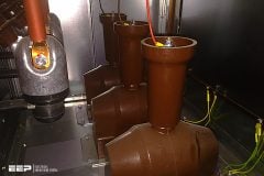
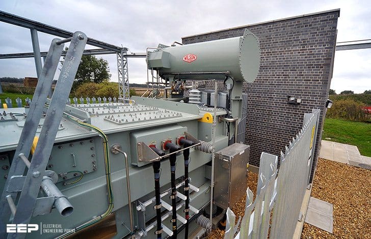 Voltage Regulators Used Control The Voltage At The End Of a Distribution Feeder (on photo: Quad booster that regulates the output voltage to a defined level; credit: Wilson Transformer Company)
At the transmission source, voltage is controlled by the voltage regulators on the generators. Voltage control equipment connected at either the supply end or the load end of the feeder would include:
- Off-load tap changing transformers,
- On-load tap-changing transformers,
- Booster transformers,
- Moving coil regulators,
- Induction regulators.
Current controlling devices intended to control the power factor are either static or rotary capacitors. Rotary capacitors are rarely if ever used in modem power systems and will not be discussed.
Voltage Changing Equipment
Tap-changing transformers are constructed so that the output voltage can be adjusted by means of a switch to increase or decrease the voltage.
Usually the voltage is changed in increments of the rated voltage – typically 2.5% for distribution (22/11 kV to 400 volt) transformers but finer, say 1.25 – 1.5% for transformers in transmission substations with a full range of adjustment up to ±10% of the rated output voltage.
This means that for an 11 kV line the voltage at the supply end can be between 9.9 kV and 12.1kV.
On-load tap-changers ensure there is no interruption to the electricity supply during the change of voltage value, and as a consequence are preferred, even though they are much more expensive. When off-load tap-changers are installed the electricity supply must be disconnected for the duration of time required to change the voltage setting.
The essential elements of the load and the compensating circuits used for the automatic control of an on-load tap-changer are shown in Figure 1.
Essentially it consists of a voltage sensing relay, which will actuate the tap-changer motor to move the tap position automatically up or down as the voltage varies away from the set desired voltage level. This set level is usually referred to as the ‘float voltage’ of the transformer or substation.
The voltage relay senses both transformer output voltage, plus a compensating voltage which reflects the drop expected in the feeder, as below.
To understand how the system works, firstly consider the simplest case, where the transformer output voltage drives the relay.
Conversely, as load falls off, the output voltage will start to rise and the voltage regulating relay will cause the transformer to change one tap back to lower the voltage and again bring it back to the desired level.
We can also compensate for the drop in the feeders going out from the substation by circulating the output of the current transformer through adjustable resistance and reactance values (which are set to reflect the resistance and reactance values of the feeder) in the voltage sensing circuit.
The drop in the model impedance Zc in the voltage regulating relay should be able to reflect the drop in voltage in the feeder, if properly set up.

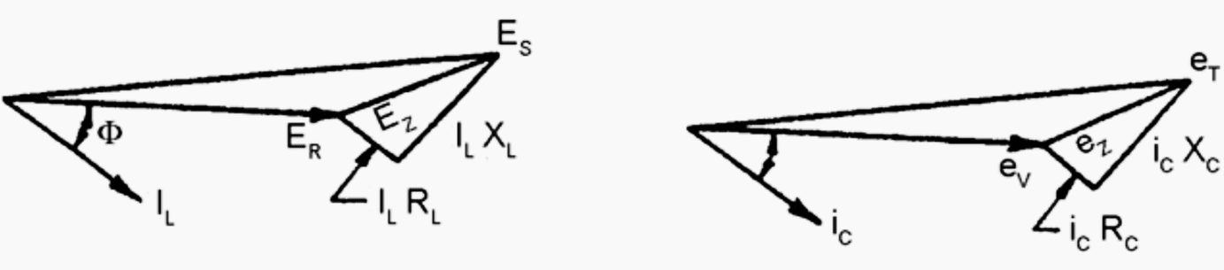
Where:
| Main Circuits | Control Circuits | ||
| ES | Sending end voltage | eT | Voltage transformer output voltage |
| EZ | Line voltage drop | eC | Compensator voltage drop |
| ER | Receiving end voltage | eV | Regulating relay voltage |
| RL | Line resistance | RC | Compensator resistance |
| XL | Line reactance | XC | Compensator reactance |
| IL | Load current | iC | CT secondary current |
The voltage sensing relay would now cause the transformer to change taps in response to variations in the voltage at the load at the end of the feeder, rather than just at the terminals of the transformers at the substation. When the load is increasing, this would mean taps would change earlier than by sensing transformer output voltage alone and the transformer output voltage would be higher, but at the load end of the feeder the voltage would be kept at the desired level.
This can be seen in the phasor diagram in Figure 1.
This compensation for the voltage drop in the line is called ‘line drop compensation’ (‘LDC’). It is usually set as a percent boost in voltage at a certain value of transformer load.
In summary, if the LDC is zero, the transformer voltage regulation relay will change taps purely on transformer terminal voltage. When the LDC is set at some positive value, the transformer voltage regulation relay will change taps based on the transformer terminal voltage less the line drop voltage value.
Types of voltage regulators
Regulators
The simplest and most commonly used method of boosting voltage on distribution lines by far, where capacity is not an issue, but where voltage variation is excessive (e.g. rural feeders) is via an auto transformer, usually simply (but not accurately) referred to as a ‘voltage regulator’ (because as we will discuss below, there are many types of regulators).
An auto transformer has one common coil instead of separate primary and secondary coils as with traditional transformers.
Output voltage can be boosted by having more turns on the output tap or reduced (‘bucked’) by having less turns on the output tap position, as shown in Figure 2.

Taps are automatically changed by an on-load tap changer described above. Another device for controlling voltage which may be used by itself or in conjunction with a transformer is a regulator, of which there are two types:
- Induction voltage regulators
- Moving coil voltage regulators
The angular position of the (stationary) shaft relative to the stator casing is controllable by means of a manually or motor driven geared wheel.
One winding (the stator) is shunt connected across the lines which need their voltage to be controlled, whilst the other winding (the rotor) is connected in series with the load or overhead line. Depending on the relative angular positions of the stator and the rotor, the shunt winding induces a voltage (v1) into the series winding, where the induced voltage may be in phase with the system voltage or may be up to 180° out of phase.
The result is that the output voltage can be varied in magnitude between the range:
(V + v1) to (V – v1)
where:
- V is the input voltage
- v1 is the injected series voltage
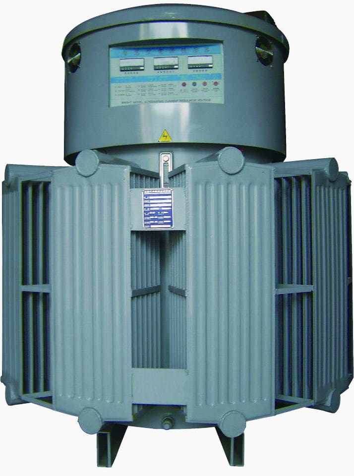
A moving coil regulator is constructed with two pairs of closely coupled shunt and series coils A1 – S1 and A2 – S2 respectively as shown in Figure 3 below.

The four coils are mounted on a common magnetic circuit, and a moving coil M is placed over the top of them. The moving coil M is short circuited onto itself, and at its limits of travel surrounds one or other of the pairs of fixed coils.
The shunt coils A1 and A2 are connected with their voltage polarity additive and the series coils S1 and S2 have their voltages in opposition. The mutual inductance of the short circuited coil M when in the top position, reduces the voltage across A1 to a minimum and increases that across A2 to a maximum.
In this case, the voltage induced into S1 is a minimum and that in S2 is a maximum. The range of control on the output voltage depends on the ratios of S2:A2 and S1:A1.
Boosters
Another less common technique for making small adjustments to line voltages uses line booster transformers. There are two type of arrangements:
- In phase booster transformers
- Quadrature (quad) booster transformers
A typical winding arrangement for an in phase booster is shown in Figure 4. The active conductors of the three phase system are indicated by AA’, BB’, CC’ respectively, and the relevant voltage levels are shown on the phasor diagram.

Three series transformers ‘a’ have their secondary windings ‘b’ connected into the lines A-A’, B-B’, C-C’. The primary windings of these transformers ‘c’ are excited from the variable outputs of the three phase transformer ‘e’ whose primary windings are connected across the line ABC in star configuration.
Quadrature boosters, or phase angle control units inject a voltage having a major component at 900 electrical to the existing line voltage. This is achieved by combining voltages from different phases instead of the same phase.
A general method of interconnection is shown in Figure 5. They are essentially a variation of the in-phase booster described above.
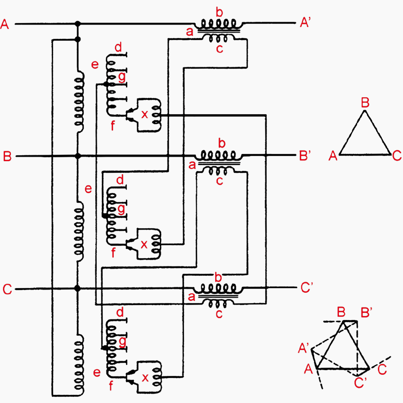
By moving the tap-changer mechanism ‘x’ from terminal ‘g’ to ‘f’ the line voltage will be increased (‘boost’) and when going from ‘g’ to ‘d’ the line voltage will be reduced (‘buck’).
This phase displacement will vary as the loads on the two feeder lines vary. When the two feeder lines are connected into the system the difference in voltages due to the phase displacement at their ends will cause a circulating current to flow.
When a quadrature booster is used at the end of one of these lines it is possible to change the distribution of current in the feeders and minimise any circulating currents.
Power factor correction
While voltage control by means of tap changing transformers is the usual method in distribution systems, power factor correcting capacitors can also have an effect on regulating voltages.
The phasor diagram Figure 6 illustrates the effects on voltage regulation by adding capacitors to a load and so changing the power factor.
The values of voltage supplied without capacitors connected is shown in full lines (ES) and with capacitors, which reduces the angle of current lag from Φ to Φ1, in dashed lines (ES1). Note how ES1 is smaller than ES, ie the voltage regulation is less.
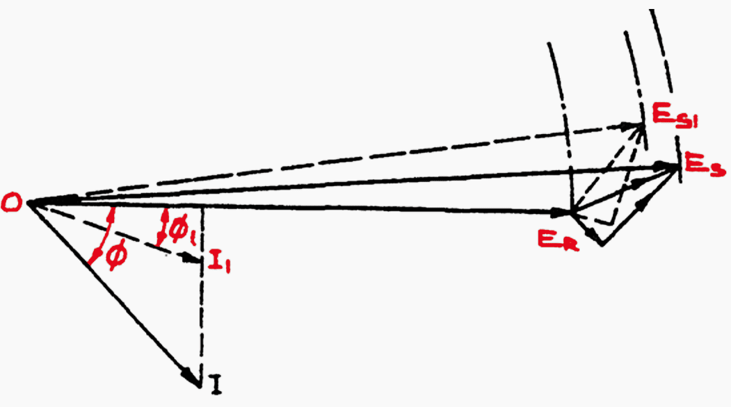
For the voltages before the capacitors are connected:
- OI = load current at uncorrected phase angle
- OER = receiving voltage or load voltage
- ERES = line voltage drop due to line current I
- OES = sending end voltage
Assuming that the load voltage ER remains constant, then:
- OI1 = load current at corrected phase angle
- OER = receiving voltage or load voltage
- ERES1 = line voltage drop due to line current I1
- OES1 = new sending end voltage
It can be seen that the phasor OES1 is less than OES, and so a lower voltage is required at the sending end to keep the load voltage constant. Normal practice is to keep the sending end voltage constant and to switch capacitors in and out at the receiving end to adjust the receiving end voltage.
Reference // Design overhead distribution systems by Chisholm Institute of TAFE
Related electrical guides & articles


Edvard Csanyi
Hi, I'm an electrical engineer, programmer and founder of EEP - Electrical Engineering Portal. I worked twelve years at Schneider Electric in the position of technical support for low- and medium-voltage projects and the design of busbar trunking systems.I'm highly specialized in the design of LV/MV switchgear and low-voltage, high-power busbar trunking (<6300A) in substations, commercial buildings and industry facilities. I'm also a professional in AutoCAD programming.
Profile: Edvard Csanyi

CONTROLLER,PUMP;ELECTRICAL DISPLACEMENT CONTROL;
125-/+18MA (DUAL COILS);ROTARY FEEDER
QTY = 1 PC
I Thank you for your up to date sharing of knowledge in the field of Electrical Engineering. I have been a fan and a close reader of your voluminous publications of specific engineering, scientific and technological knowledge.
Thank you once again!
hi thanks for the information and posts
How often do these voltage regulators fail on a three phase system with 4800 volts?
Is it possible for insects to enter and cause failure? Or rodents? Snakes?
This is a serious request for information. Thank you. Nikki.
Dear,
I am thinking , Is it possible for you guy’s to publish Electrical and Electronic Engineering lecture notes or handbook with engineering mathematics which is related to that ?