
Estimated Study Time: 28 minutes
Voltage Transformer Selection Scheme
In substations, voltage transformers (VTs) are used extensively for energy metering, protection relay operations, and synchronization checks. Their design includes multiple cores, each dedicated to specific functions. For instance, a protection core, typically labeled 3P, offers acceptable accuracy for fault detection, while a metering core, such as 0.2S, provides the high precision required for energy accounting.
 Voltage transformer selection scheme in complex substations
These cores must be selected and utilized appropriately to meet the operational demands of the substation.
A voltage transformer selection scheme ensures that the correct secondary voltage is routed to the relevant devices, especially in substations with complex configurations like double busbar systems. Synchronization, a critical operation, relies on VTs to provide voltage signals from both the line and busbar sides of a circuit breaker.
This process ensures that two electrical systems can be safely connected by matching their voltages, frequencies, and phase angles.
In an era where power systems demand greater efficiency and reliability, VT selection schemes represent a cornerstone of modern substation engineering. They enable precise synchronization and protection while optimizing resources, ensuring that substations meet the evolving needs of the energy industry.
- Voltage Transformer:
- Exploring VT Selection Scenarios:
- Overview of the Double Busbar Scheme:
- Key Considerations in VT Selection Design:
- Case Studies: Detailed VT Selection in Action for MV Switchgear
- Designing the MV SWGR without VT Selection Scheme
- Designing the MV SWGR with VT Selection Scheme
- Incomer 1 Operation: Detailed Analysis
- Case #1: Bus Coupler 1 is Open
- Case #2: Bus Coupler 1 is Closed, Incomer 2 is Closed, and Bus Coupler 2 is Open
- Case #3: Bus Coupler 1 and Bus Coupler 2 are Closed, Incomer 2 is Open, and Incomer 3 is Closed
- Bus Coupler 1 Operation: Detailed Analysis
- Case #1: Bus Coupler 2 is Open
- Case #2: Bus Coupler 2 is Closed
- Possible Logics for VT Selection
- Importance of VT Selection for Design Efficiency
- VT Selection Logic for Three Incomers and Two Bus Couplers
- BONUS 🔗 Download Guide: Equipment and Systems Utilized in the Electrical Power Generation Industry
1. Voltage Transformer (VT)
1.1 Role of Voltage Transformers in Substations
Voltage Transformers play a critical role in substations by stepping down high primary voltages to safe, measurable levels suitable for use by control, protection, and measurement devices. VT consist of two windings: the primary winding, connected to the high-voltage system, and the secondary winding, which provides the stepped-down voltage output for various applications.
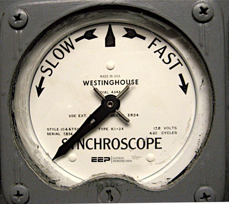
1.2 Synchro-Check Operation
When connecting two different power sources—such as a line to a bus—it is crucial to perform a synchro-check operation. This operation ensures that:
- Voltage Magnitude: The voltages on both sides of the breaker are approximately equal.
- Frequency: The frequencies of the two sources match.
- Phase Angle: The phase angles are aligned within acceptable limits.
Voltage Transformers provide the necessary voltage inputs for synchro-check relays to perform this critical function.
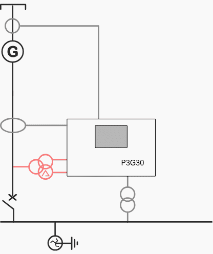
Figure 1 – Protection of a generator coupled to another source with Easergy P3 (Synchro-check via VTs included)
1.3 VT Cores and Accuracy Classes
Voltage Transformers are typically designed with multiple cores, each dedicated to a specific purpose, such as protection or measurement. Refer to Figure 2 for an example single-line diagram showing a VT and its core classes.
Here’s a detailed explanation:
Protection Core (3P):
The “3P” designation indicates a protection core. The “P” stands for “Protection,” and the “3” specifies the percentage error, meaning the protection core can have an error of up to 3%.
Measurement Core (0.2S):
The “0.2S” designation represents a measurement core. The “0.2” refers to the allowable or rated percentage error, ensuring high accuracy for metering applications.
Measurement cores are designed to provide precise voltage signals to ensure accurate energy measurement and system monitoring.
Figure 2 – Single line diagram showing voltage transformer with multicore option

1.4 Why is a VT Selection Scheme Required?
Voltage Transformer (VT) selection schemes are essential for ensuring the correct operation of synchronization checks (synch-check) during breaker closing operations. These schemes determine which VT secondary voltages should be fed to the synch-check relay, enabling proper synchronization of different voltage sources.
Let’s explore why VT selection is necessary and when it is employed.
1.5 Synchronization and the Role of VT’s
When closing a circuit breaker to connect two systems, such as a transmission line to a busbar, it is critical to ensure that the voltages on either side of the breaker are synchronized. Synchronization requires matching voltage magnitude, phase angle, and frequency between the two systems.
Each VT monitors the voltage of a specific system element—such as a line or a busbar—and transmits this information to the synch-check relay. The relay compares the voltages of the two systems and determines whether the breaker can be safely closed.
Further Study – Synchronization and Reactive Power Control in Power System
1.6 When VT Selection Is Not Required
In simple systems with a limited number of voltage sources, a dedicated VT can be directly connected to the synch-check relay for each system element. This approach works well for straightforward setups where there is no need to switch between multiple sources.
For example, in a single-line-to-bus synchronization scenario, a single VT on the line side and another on the bus side might suffice, eliminating the need for a selection scheme.
However, this simplicity comes at the cost of installing and maintaining multiple VTs, which may not be cost-effective for more complex systems.
1.7 Benefits of VT Selection Scheme
In larger substations or medium-voltage switchgear setups with multiple lines and buses, installing a dedicated VT for each system element can become impractical and expensive. VT selection schemes address this issue by allowing a single synch-check relay to use the secondary voltages from multiple VT’s.
Key reasons for employing VT selection schemes include:
Key #1 – Cost Optimization:
Reducing the number of VT’s by sharing them between multiple lines or buses minimizes equipment costs without compromising functionality.
Key #2 – Flexibility in Operations:
VT selection schemes offer greater operational flexibility by enabling the synch-check relay to dynamically select the required voltage sources based on the breaker’s position or the specific synchronization scenario.
Key #3 – Efficient Space Utilization:
In space-constrained environments, such as medium-voltage switchgear, using fewer VT’s and employing a selection scheme helps optimize the layout.
Learn more – MV switchgear: Important design considerations & applications
Medium voltage switchgear: Important design considerations and applications
2. Exploring VT Selection Scenarios
The next sections will delve into different scenarios and applications of VT selection schemes, examining how they are implemented in various substation configurations. Understanding these scenarios will provide deeper insights into the technical and economic benefits of VT selection schemes.
2.1 How to design the VT Selection Scheme?
Voltage Transformer (VT) secondary selection is an integral part of substation schemes, ensuring that the appropriate VT secondary voltages are fed to devices such as synch-check relays. This selection is particularly important in substations employing double busbar configurations, where flexibility in choosing the active busbar is essential for operational efficiency.
In this section, we will explore the VT secondary selection process in detail using NO and NC contacts.
3. Overview of the Double Busbar Scheme
In a double busbar configuration, each bus is equipped with its own VT to monitor the voltage on that bus. The system includes isolators (or disconnect switches) that connect the line to either Bus 1 or Bus 2. VT secondary selection ensures that the synch-check relay receives the correct voltage signals from the active busbar, depending on the state of the isolators.
3.1 Schematic Description of VT Selection in Double Busbar Scheme
1. VT for Each Busbar:
Each busbar (Bus 1 and Bus 2) has its own VT. The secondary windings of these VTs are wired to the busbar isolators associated with the line. For example, VT1 monitors the voltage on Bus 1, and VT2 monitors the voltage on Bus 2.
Related electrical guides & articles


Muhammad Kashif
Muhammad Kashif Shamshad is an Electrical Engineer and has more than 17 years of experience in operation & maintenance, erection, testing project management, consultancy, supervision, and commissioning of Power Plant, GIS, and AIS high voltage substations ranging up to 500 kV HVAC & ±660kV HVDC more than ten years experience is with Siemens Saudi Arabia.Profile: Muhammad Kashif
