Irreplaceable in Power Circuits
The most common voltage sources for power system measurements and protections are either wound transformers (voltage transformers) or capacitive divider devices (capacitor voltage transformers or bushing potential devices). Some new applications of resistor dividers and magneto-optic technologies are also becoming available.
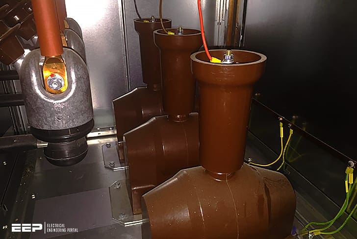
All provide scaled replicas of their high-voltage potential. They are characterized by their ratio, load capability, and phase-angle response. Wound potential transformers (PTs) provide the best performance with ratio and phase-angle errors suitable for revenue measurements.
Even protection-type voltage transformers can provide revenue-metering performance if the burden is carefully controlled.
For substation automation purposes, VTs are unaffected by changes in load or temperature. They are the preferred source for measuring potential.
This technical article will explain all important aspects of voltage transformers in MV and HV measurement and protection applications.
- Simple equivalent circuit of voltage transformer
- Electromagnetic Voltage Transformers
- Capacitor Voltage Transformers (CVT)
1. Simple equivalent circuit of voltage transformer
Voltage transformer can be represented by the equivalent circuit of Figure 1, where all quantities are referred to the secondary side.
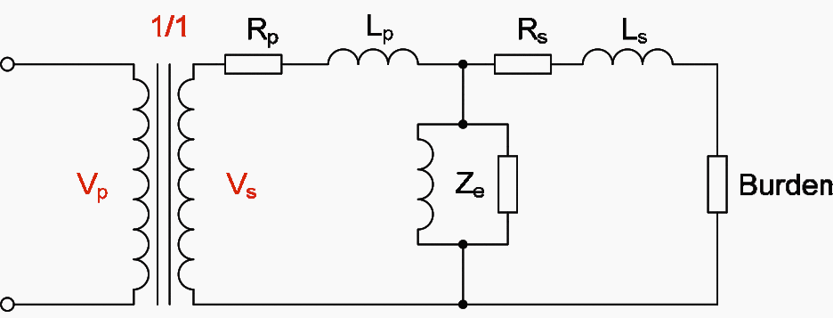

When voltage transformer is not 1/1 ratio, this condition can be represented by energizing the equivalent circuit with an ideal transformer of the given ratio but having no losses.
Voltage transformers behave similar to small power transformers, with difference only in details of design that control ratio accuracy over the specified range of output.
2. Electromagnetic Voltage Transformers
In the shunt mode, the system voltage is applied across the input terminals of the equivalent circuit of Figure 1. The vector diagram for this circuit is shown in Figure 2.


The secondary output voltage Vs is required to be an accurate scaled replica of the input voltage Vp over a specified range of output.
These limitations in design result in a VT for a given burden being much larger than a typical power transformer of similar rating. Consequently the exciting current is not as small, relative to the rated burden, as it would be for a typical power transformer.
2.1 Ratio and Phase Errors
The ratio and phase errors of the transformer can be calculated using the vector diagram of Figure 2 above. The ratio error is defined as:


where:
- Kn is the nominal ratio
- Vp is the primary voltage
- Vs is the secondary voltage
If the error is positive, the secondary voltage is greater than the nominal value. If the error is negative, the secondary voltage is less than the nominal value.
The phase error is the phase difference between the reversed secondary and the primary voltage vectors. It is positive when the reversed secondary voltage leads the primary vector.
Requirements in this respect are set out in IEC 60044-2. All voltage transformers are required to comply with one of the classes in Table 1.
Table 1 – Measuring Voltage Transformer error limits
| Accuracy class | 0.8 – 1.2 × rated voltage 0.25 – 1.0 × rated burden at 0.8pf | |
| voltage ratio (%) | Phase displacement (minutes) | |
| 0.1 | +/- 0.1 | +/- 5 |
| 0.2 | +/- 0.2 | +/- 10 |
| 0.5 | +/- 0.5 | +/- 20 |
| 1.0 | +/- 1.0 | +/- 40 |
| 3.0 | +/- 3.0 | not specified |
For protection purposes, accuracy of voltage measurement may be important during fault conditions, as the system voltage might be reduced by the fault to a low value.
Voltage transformers for such types of service must comply with the extended range of requirements set out in Table 2.
Table 1 – Additional limits for protection Voltage Transformers
| Accuracy class | 0.25 – 1.2 × rated voltage 0.05 – Vf × rated primary voltage | |
| voltage ratio (%) | Phase displacement (minutes) | |
| 3P | +/- 3.0 | +/- 120 |
| 6P | +/- 6.0 | +/- 240 |
2.2 Voltage Factors
The quantity Vf in Table 2 is an upper limit of operating voltage, expressed in per unit of rated voltage. This is important for correct relay operation and operation under unbalanced fault conditions on unearthed or impedance earthed systems, resulting in a rise in the voltage on the healthy phases.
Table 3 – Voltage transformers permissible duration of maximum voltage
| Voltage factor Vf | Time rating | Primary winding connection/system earthing conditions |
| 1.2 | continuous | Between lines in any network |
| Between transformer star point and earth in any network | ||
| 1.2 | continuous | Between line and earth in an effectively earthed network |
| 1.5 | 30 sec. | |
| 1.2 | continuous | Between line and earth in a non-effectively earthed neutral system with automatic earth fault tripping |
| 1.9 | 30 sec. | |
| 1.2 | continuous | Between line and earth in an isolated neutral system without automatic earth fault tripping, or in a resonant earthed system without automatic earth fault tripping |
| 1.9 | 8 hours |
2.3 Secondary Leads
Voltage transformers are designed to maintain the specified accuracy in voltage output at their secondary terminals. To maintain this if long secondary leads are required, a distribution box can be fitted close to the VT to supply relay and metering burdens over separate leads.
If necessary, allowance can be made for the resistance of the leads to individual burdens when the particular equipment is calibrated.
2.4 Protection of Voltage Transformers
Voltage Transformers can be protected by High Rupturing Capacity (H.R.C.) fuses on the primary side for voltages up to 66kV. Fuses do not usually have a sufficient interrupting capacity for use with higher voltages. Practice varies, and in some cases protection on the primary is omitted.
A short circuit on the secondary circuit wiring produces a current of many times the rated output and causes excessive heating. Even where primary fuses can be fitted, these usually do not clear a secondary side short circuit because of the low value of primary current and the minimum practicable fuse rating.
2.5 Construction of Voltage Transformers
The construction of a voltage transformer differs from that of a power transformer in that different emphasis is placed on cooling, insulation and mechanical design. The rated output seldom exceeds a few hundred VA and therefore the heat generated normally presents no problem.
The size of a VT is largely determined by the system voltage and the insulation of the primary winding often exceeds the winding in volume.
Voltage transformers are commonly used with switchgear so the physical design must be compact and adapted for mounting in or near to the switchgear. Three-phase units are common up to 36kV but for higher voltages single-phase units are usual.
Voltage transformers for medium voltage circuits have dry type insulation, but high and extra high voltage systems still use oil immersed units.
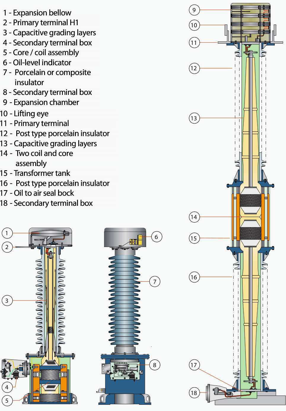
Figure 3 shows an Alstom OTEF 36.5kV to 765kV high voltage electromagnetic transformer.

2.6 Residually connected Voltage Transformers
The three voltages of a balanced system summate to zero, but this is not so when the system is subject to a single-phase earth fault. The residual voltage of a system is measured by connecting the secondary windings of a VT in ‘broken delta’ as shown in Figure 4.
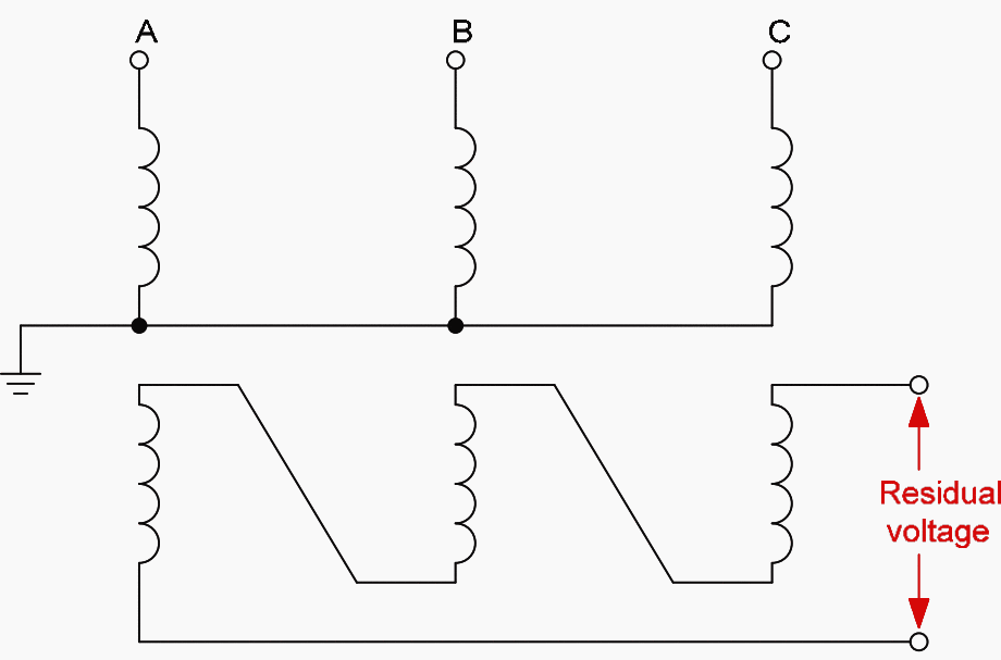

The output of the secondary windings connected in broken delta is zero when balanced sinusoidal voltages are applied, but under conditions of imbalance a residual voltage equal to three times the zero sequence voltage of the system is developed.
To measure this component it is necessary for a zero sequence flux to be set up in the VT, and for this to be possible there must be a return path for the resultant summated flux.
The VT core must have one or more unwound limbs linking the yokes in addition to the limbs carrying windings. Usually the core is made symmetrically, with five limbs, the two outermost ones being unwound. Alternatively, three single-phase units can be used.
It is equally necessary for the primary winding neutral to be earthed, for without an earth, zero sequence exciting current cannot flow.
A VT should be rated to have an appropriate voltage factor as described in Section 1.2 and Table 3, to cater for the voltage rise on healthy phases during earth faults.
Alternatively the residual voltage can be extracted by using a star/broken-delta connected group of auxiliary voltage transformers energized from the secondary winding of the main unit, providing the main voltage transformer fulfills all the requirements for handling a zero sequence voltage as previously described.
The auxiliary VT must also be suitable for the appropriate voltage factor. It should be noted that third harmonics in the primary voltage wave, which are of zero sequence, summate in the broken-delta winding.
2.7 Transient Performance
Transient errors cause few difficulties in the use of conventional voltage transformers although some do occur. Errors are generally limited to short time periods following the sudden application or removal of voltage from the VT primary.
If a voltage is suddenly applied, an inrush transient occurs, as with power transformers. However, the effect is less severe than for power transformers because of the lower flux density for which the VT is designed. If the VT is rated to have a fairly high voltage factor, there is little inrush effect.
An error appears in the first few cycles of the output current in proportion to the inrush transient that occurs.
If the exciting quantity in ampere-turns exceeds the burden, the transient current may be significant.
2.8 Cascade Voltage Transformer
The capacitor VT (described in next section) was developed because of the high cost of conventional electromagnetic voltage transformers but, as shown in Section 2.2 above, the frequency and transient responses are less satisfactory than those of the orthodox voltage transformers.
Another solution to the problem is the cascade VT shown in Figure 5.


The conventional type of VT has a single primary winding, the insulation of which presents a problem for voltages above about 132kV. The cascade VT avoids these difficulties by breaking down the primary voltage in several distinct and separate stages.
The complete VT is made up of several individual transformers, the primary windings of which are connected in series as shown in Figure 5.
- Each magnetic core has primary windings (P) on two opposite sides.
- The secondary winding (S) consists of a single winding on the last stage only.
- Coupling windings (C ) connected in pairs between stages, provide low impedance circuits for the transfer of load ampere-turns between stages and ensure that the power frequency voltage is equally distributed over the several primary windings.
The potentials of the cores and coupling windings are fixed at definite values by connecting them to selected points on the primary windings. The insulation of each winding is sufficient for the voltage developed in that winding, which is a fraction of the total according to the number of stages.
The individual transformers are mounted on a structure built of insulating material, which provides the interstage insulation, accumulating to a value able to withstand the full system voltage across the complete height of the stack.
The entire assembly is contained in a hollow cylindrical porcelain housing with external weather-sheds; the housing is filled with oil and sealed, an expansion bellows being included to maintain hermetic sealing and to permit expansion with temperature change.
3. Capacitor Voltage Transformers (CVTs)
The size of electromagnetic voltage transformers for the higher voltages is largely proportional to the rated voltage. The cost tends to increase at a disproportionate rate.
The capacitor voltage transformer (CVT) is often more economic. This device is basically a capacitance potential divider. As with resistance-type potential dividers, the output voltage is seriously affected by load at the tapping point.
A reactor possesses some resistance, which limits the output that can be obtained. For a secondary output voltage of 110V, the capacitors would have to be very large to provide a useful output while keeping errors within the usual limits. The solution is to use a high secondary voltage and further transform the output to the normal value using a relatively inexpensive electromagnetic transformer.
The successive stages of this reasoning are shown in Figure 6 below.


There are numerous variations of this basic circuit. The inductance L may be a separate unit or it may be incorporated in the form of leakage reactance in the transformer T. Capacitors C1 and C2 cannot conveniently be made to close tolerances, so tappings are provided for ratio adjustment, either on the transformer T, or on a separate auto-transformer in the secondary circuit.
Adjustment of the tuning inductance L is also needed. This can be done with tappings, a separate tapped inductor in the secondary circuit, by adjustment of gaps in the iron cores, or by shunting with variable capacitance.
A simplified equivalent circuit is shown in Figure 7 below.


The main difference between Figure 7 and Figure 1 is the presence of C and L. At normal frequency when C and L resonate and therefore cancel, the circuit behaves in a similar way to a conventional VT.
However, at other frequencies a reactive component exists which modifies the errors.


Standards generally require a CVT used for protection to conform to accuracy requirements of Table 2 within a frequency range of 97-103% of nominal.
The corresponding frequency range of measurement CVTs is much less, 99%-101%, as reductions in accuracy for frequency deviations outside this range are less important than for protection applications.
3.1 Voltage Protection of Auxiliary Capacitor
If the burden impedance of a CVT is short-circuited, the rise in the reactor voltage is limited only by the reactor losses and possible saturation to:
Q × E2
where
- E2 is the no-load tapping point voltage and
- Q is the amplification factor of the resonant circuit.
This value would be excessive and is therefore limited by a spark gap connected across the auxiliary capacitor. The voltage on the auxiliary capacitor is higher at full rated output than at no load, and the capacitor is rated for continuous service at this raised value.
Usually the tapping point can be earthed either manually or automatically before making any adjustments to tappings or connections.
3.2 Transient Behaviour of Capacitor Voltage Transformers
A CVT is a series resonant circuit. The introduction of the electromagnetic transformer between the intermediate voltage and the output makes further resonance possible involving the exciting impedance of this unit and the capacitance of the divider stack.
When a sudden voltage step is applied, oscillations in line with these different modes take place and persist for a period governed by the total resistive damping that is present. Any increase in resistive burden reduces the time constant of a transient oscillation, although the chance of a large initial amplitude is increased.
However, high performance protection schemes may still be adversely affected unless their algorithms and filters have been specifically designed with care.
3.3 Ferro-Resonance
The exciting impedance Ze of the auxiliary transformer T and the capacitance of the potential divider together form a resonant circuit that usually oscillates at a sub-normal frequency. If this circuit is subjected to a voltage impulse, the resulting oscillation may pass through a range of frequencies.
If the basic frequency of this circuit is slightly less than one-third of the system frequency, it is possible for energy to be absorbed from the system and cause the oscillation to build up.
The increasing flux density in the transformer core reduces the inductance, bringing the resonant frequency nearer to the one-third value of the system frequency.
Depending on the values of components, oscillations at fundamental frequency or at other sub-harmonics or multiples of the supply frequency are possible but the third subharmonic is the one most likely to be encountered. The principal manifestation of such an oscillation is a rise in output voltage, the r.m.s. value being perhaps 25% to 50% above the normal value.
The output waveform would generally be of the form shown in Figure 9.
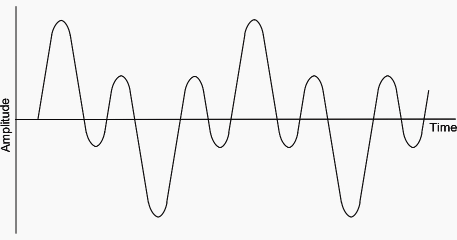

Such oscillations are less likely to occur when the circuit losses are high, as is the case with a resistive burden, and can be prevented by increasing the resistive burden.
Correct design prevents a CVT that supplies a resistive burden from exhibiting this effect, but it is possible for non-linear inductive burdens, such as auxiliary voltage transformers, to induce ferro-resonance.
Auxiliary voltage transformers for use with capacitor voltage transformers should be designed with a low value of flux density that prevents transient voltages from causing core saturation, which in turn would bring high exciting currents.
Sources:
- Network protection and automation guide by (ex) Alstom Grid, now General Electric
- Electric Power Substations Engineering By James C. Burke


1. Table2 is shown as Table1. Pls check.
2. In Section 2.8, sentence is refer secton2.2 but there is no relation. Pls check
This is helpful to me though i am just a beginner.
Excellent work!
However, I have a doubt …
You point out that…”The increasing flux density in the transformer core reduces the inductance,…”
Can you explain why this statement?
From my point of view and based on the theory, the flux is proportional to the inductance, therefore if there is an increase in flux it will also increase the inductance but it would not reduce
Hope you can clear this doubt
I appreciate your experience ………..
I want to thank you specially for giving us this wonderful EEP reports. How do I pay for premium
Thank you Alex. We use Paypal and Payoneer services for payments. Membership levels and more info you can find here:
https://electrical-engineering-portal.com/membership-account/membership-levels
Very useful tqq u so much
good job