Partial discharges are electrical discharges occuring in insulating materials. The electrical discharge’s path only spans part of the insulating distance separating the conductors. The problem of partial discharges, whilst not existing in Low Voltage, is found in High and Very High Voltage.
Partial discharges can occur in cavities within solid insulants, in gas bubbles in liquid insulants, or between different layers of insulation, should these layers have different dielectric properties.
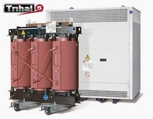
This is why immersed type transformers are filled under vacuum and why Trihal cast resin transformers are vacuum cast. They can also occur on points or sharp edges of live metal surfaces.
What are the consequences ?
Whilst only involving small amounts of energy, partial discharges may lead to the progressive deterioration of the insulating materials’ dielectric properties. This is why it is essential to make sure that electrical equipment is not prone to partial discharges under its conditions of usage.
How are they characterised and measured ?
Partial discharges generally come in the form of individual impulses that can be detected as electrical impulses in an external circuit connected to the transformer during an induced voltage test.
Partial discharges cause high frequency signals that are easily separated from the industrial frequency voltage by filtering. Interference from high frequency parasites may affect partial discharge measurement. These high frequency parasites cause a background noise which determines the value below which partial discharge levels are not possible to measure.
During tests on the transformer, the partial discharge are by “the magnitude of their apparent charge” represented by the symbol “q“. The apparent charge of a partial discharge, is the quantity of electricity that, if instantly injected across the two terminals of the transformer under test, would produce the same effect on the measuring device as the partial discharge itself.
The magnitude of “q” is the absolute value of the apparent charge. It is measured in pico-Coulombs [pC].
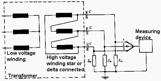
- Coupling capacitors C in series with detector impedance’s Zm, to enable uncoupling of both the high voltage of the transformer under test and the high frequency partial discharges.
- A detector to amplify the partial discharge impulses and to show the value of the largest discharge’s magnitude.
Below is shown an example of the wiring diagram of the partial discharge measuring circuit for a three-phase transformer.

SOURCE: France Transfo by Schneider Electric


hank you for the information, but how to measure the high voltage and impedance specified formula counts the value capasitornya be fitted on the circuit in order to secure the measuring instrument.