Design challenges
There are several locations where conduit is used in power substation designs. The most common one considered is conduit used to provide cable access to equipment, such as breakers, transformers, instrument transformers, and motor-operated disconnect switches located in the yard of the substation.

Conduit can be a means by which direct buried cable gets from the ground to the equipment, or it can be run directly to cable trenches, manholes, or to the electrical equipment enclosure. Conduit is also used to run the wiring within the electrical equipment enclosure.
Utilization wiring would include AC power cable used for lighting receptacles and HVAC. These uses of conduit are in all substations and have a straightforward application of the NEC.
Another application of conduit in the substation is for the protection of medium-voltage circuits. Examples of these circuits include distribution cable leaving the substation and wind farm collector circuits entering the substation. This application of conduits results in some design challenges when applying the NEC.
One common type of conduit used for the below-grade conduit in the substation is PVC.
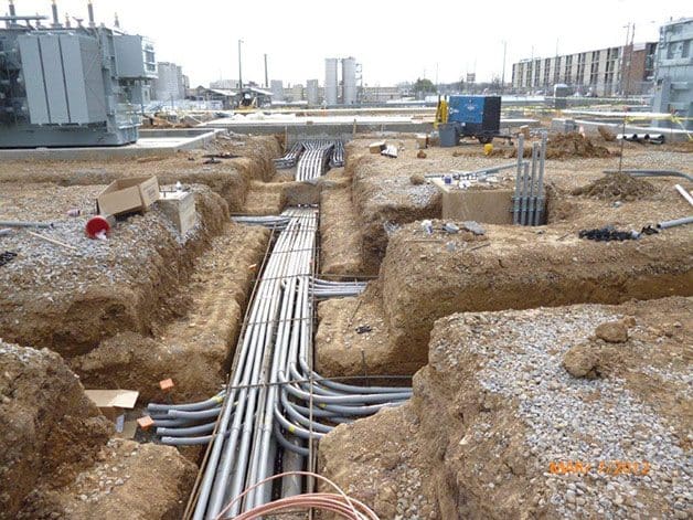
NEC Article 352 applies to PVC conduit. PVC conduit is corrosion resistant and therefore used for many below-grade applications. It can be direct buried or encased in concrete.
At substation equipment, a transition from a non-metallic conduit to a metallic conduit is usually made. Type RMC, or rigid metal conduit (generally galvanized steel), is used for the above-grade conduit connection to substation equipment in the yard. NEC Article 344 applies to rigid metal conduit.
In northern climates, another consideration for conduit installations to equipment in the yard is frost. Frost depths there can reach up to four feet deep. Heaving related to the frost can cause conduit to push or pull equipment cabinets. The NEC provides articles on the use of these types of installations (Sections 300.7(B) and 250.98).
A few examples that may help minimize the upward movement of conduit into enclosures include; using flexible conduit or expansion fittings, and site grading practices or local foundation correction (i.e. deep sand layer).
The design engineer should consult with the requirements for frost depth in each state, as it can also impact the burial depth of the conduit.
While the substation design engineer will usually select the conduit type, routing, and sizing of the conduit used for the substation equipment in the yard, the conduit used within the electrical equipment enclosure will be selected and installed by the electrician or electrical equipment enclosure manufacturer.
EMT will generally be routed on the walls inside the electrical equipment enclosure. When installed with proper fittings, it can be used as the equipment grounding conductor. However, running a separate equipment grounding conductor with the phase conductor(s) to lights or receptacles within the electrical equipment enclosure is preferred. See Article 358 for requirements pertaining to EMT conduit.
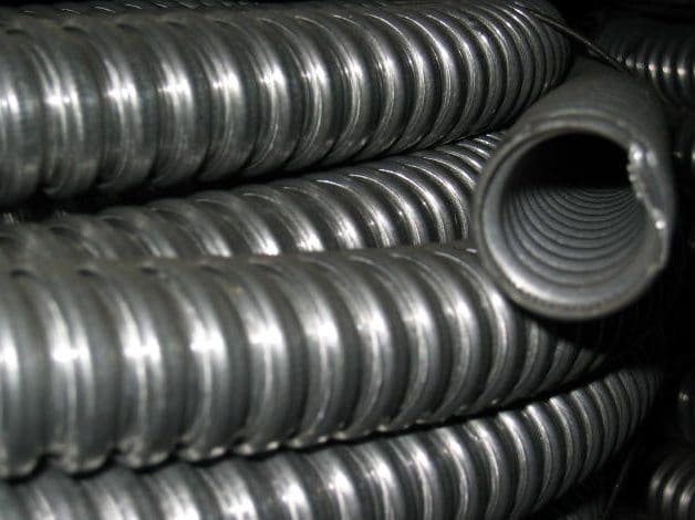
The typical design of a conduit system will include conduit burial depth, bending radius, calculations on conduit fill, and determination of cable ampacity de-rating. Each of these criteria is covered in the NEC. Along with these design considerations, installation considerations are also addressed by the NEC, such as how the conduit is to be supported and secured.
This NEC section covers the burial depth for cable and conduit. While the NEC permits PVC conduit to be installed at a depth of 18”, consideration must also be given to local codes, frost depth, cable ampacity, and the conduit bending radius. The bending radius for each trade size of conduit is covered in Table 2 of Chapter 9 in the NEC.
Circuits exceeding 600V have additional depth requirements and are covered under Section 300.50 of the NEC. PVC conduits used for circuits from 22kV to 40kV are required to be at least 24” deep. The increased depth must also be taken into account when calculating ampacity of the cables within the conduit, see NEC Section 310.60(C)(2).
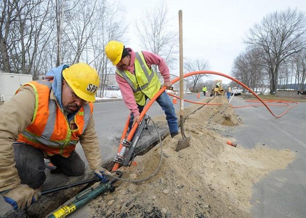
Maximum fill percentages for conduit are covered in Table 1 of Chapter 9 in the NEC.
It is important to consider the length of the conduit run and the number of bends in the conduit runs when determining the amount of fill that is acceptable. The maximum fill percentage will not guarantee an easy installation. Other considerations associated with the fill of the conduit and the ease of installation is the jamming ratio. While the NEC does not govern this, it does contain an informational note about its occurrence.
There are many different requirements for ampacity de-rating of cables, but specific to conduit is NEC Section 310.15(B)(3)(a), which addresses the number of current carrying conductors in a raceway.
Ampacity for cables can be required to be reduced to 35% of the original value. This section has several exceptions that should be examined for each application to reduce oversizing cable.
As mentioned above, there can be challenges when applying the NEC to larger underground medium voltage circuits. In order to meet the fill requirements of the NEC, PVC conduit sizes larger than 6” are often required for the cable used.
The maximum size PVC conduit allowed by NEC is 6”. While manufacturers do produce 8” conduit, it is not acceptable to use it in conjunction with the NEC, and it will not usually be UL listed. It is up to the engineer to work with the authority having jurisdiction to determine if the use of 8” conduit is acceptable.
The NESC also contains a section on underground conduit systems in respect to the installation and maintenance of underground electric supply and communication lines that should be considered.
Reference: Applying the National Electrical Code to Substations – Jeff Heinemann, Mark Scheid





Nice and amazing post you shared with us.
Hi, everybody,
I’m a new member here, and this is my first post. I hope that perhaps someone can share some opinions based on experience or knowledge of the NESC and NEC for my current situation.
I have several questions and I need to know your opinions
There is a job where you have to take a 13.8 kV three-phase power supply and install a 500 kVA transformer, with 208Y/3PH/60Hz secondary. As a second service input.
The project owner says he wants to take the lines, from the overhead line poles by twisting the #2 XLPE cable with Concentric Neutral to the wall of an industrial warehouse, and take them from the entry cap, so horizontally, over the eaves, about 525 feet, anchored to the concrete block wall, and then down to the transformer. The measurement would be primary, and would be on the pole, as would the switches and fuses. After the transformer a 2000 A switch, and the rest as usual.
The owner of the project, who worked in a public utility company, says this can be done.
It seems to me that the MV lines can be placed, by embedding in concrete, electric conduit at the foot of the entire length of the loading platform, on the concrete floor, until very close to the transformer, where it would be connected to the transformer’s passage vault. According to NEC 230.6(2)
I am not familiar with the NESC, but it seems to me that laying 13.8 kV lines, in PVC conduits, superficially anchored to a wall, is not very safe.
thanks
Thanks
Thanks, I
Can you please guide me how to calculate the Trench size for under ground cables from Transformer (owner premises) to LV panel. For a specific case there are 9 nos of 1C 630mm² cables. please guide me.
useful information for me
Very informative..
The article as well as the comments by Mr George and Mr Alexander are quite helpful for budding engineers in this field. Please keep posting.
Regards
Hello, thanks for the article, was very helpful. I believe, for what I see of the picture that’s not PVC conduit, looks metallic conduit maybe IMC or RMC.
Nevermind, sorry by the bending in the length it shows is PVC. Thanks again
I have been an electrical engineer/ designer for over 40 yers and [ossessa diverse background in industries and intra-plant power for architectural, power genertion, mining, DoD, DoE and other facilities. I have been hired via a “job shop” to debug a design that shold not habve been isued for conmstructioon prior to a thorough audit. Too many junior engineers are ignorant of the mathematics and electrical theory that is the basis of the computerized design and calculation programs. They are proficient with the software but do not understand the basic power triangle or the tigonometry behind it.
Most are oblivious to the NEC, CEC or IEC, as the respective codess and safety standards that any engineer or designer should know or know haw to use. Each application is unique as to ambient temperature, cable spacing, number of conductors, depth of raceway for underground, effects of ambient temperature on conductor derating, etc. Grounding systems are not “one size fits all.” They must be assessed by someone or firm tha knows how to conduct soil resitivity tests at the respective site. I have had to redisign electrical systems that were creted by someone who did not know the NEC or other codes, much less understand that the brake horsepower of a motor is not the same as the motor horsepower rating.
I have virtually written off engineering and am looking for an alternative career, as I found too many recruiters who tag me as “overqualified.” They either are intimidted by someone with three times their experience or want to low ball their wages and hope that an inferior design is not created.
George you should look into university career and make sure those grads have the knowledge and the understanding!