
Estimated Study Time: 17 minutes
Transformer Load Tap Changer (LTC)
We all experienced the ocasional flickering of the house lights during evenings. This usually indicates a load tap changer (LTC) adjustment, or a sign that the bulb is about to drop dead, but that’s not the subject of this article :). Upon returning home from work, the majority of individuals commence utilizing electricity for culinary and lighting purposes.
 What is a Load Tap Changer - LTC? (photo credit: Stadtwerke Rostock AG)
This elevates the electrical demand on the distribution network, resulting in a voltage drop below its nominal value. The latter instructs the LTC to change the taps in order to restore the voltage to its nominal value within specified tolerances.
Transformers have numerous applications in contemporary electric power systems, including generator step-up, system interconnection, distribution, arc furnaces, and HVDC converters, among others. A transformer’s function is to convert electrical energy between different voltage levels.
Each transformer installed in an electrical network has an ideal voltage ratio for optimal system operation. However, this ideal voltage ratio fluctuates based on the operational conditions of the entire electrical network. In the early development of electric power networks, it became clear that transformer voltage ratios must be changeable to ensure satisfactory operation without disrupting energy flow.
This defines what is expected of a Load Tap Changer (LTC).
So, what is a LTC?
An LTC – load tap changer is an equipment that belongs to the transformer, and it interlinks several taps of transformer windings without disrupting the load. An LTC makes transition between tap positions without interrupting the current flow to the load or causing a short circuit between any two taps of the transformer winding.
Transformers with tap-changer serve to regulate voltage, phase angle, or both within a regulated circuit.
A Load Tap Changer (LTC) comprises four components:
- A selector switch that enables the choosing of the active tap.
- A changeover switch, often known as a reversing switch because it alters the polarity of the tapped winding, is employed to increase the number of available positions.
- A transition mechanism, comprising an arcing or diverter switch, that facilitates the shift from one tap to another.
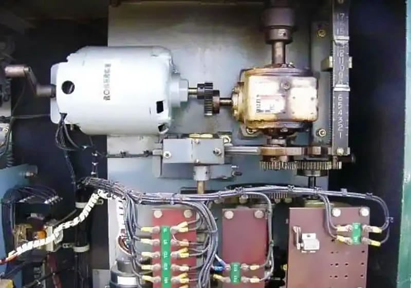
- A driving mechanism, consisting of a motor, gearbox, and controls, that operates the system.
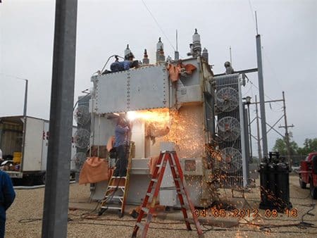
Figure 1 – Replacing load tap-changers
There exist two fundamental categories of tap changers:
1. Tap changers inside the transformer tank:
The Jansen type, a cover-mounted, in-tank tap changer, is positioned within the main transformer oil beside the core-and-coil assembly. The selector and changeover switches are located at the bottom of the tap changer within the main oil tank.
The arcing (diverter) switch is situated in a distinct compartment at the the top, typically within a sealed cylinder composed of fiberglass or a comparable material.
All arcing is restricted to this compartment. They are available in single-phase or three-phase neutral end Wye (Y)-connected configurations. Three single-phase tap changers are required for three-phase fully insulated installations. This variant of tap changer is employed for higher voltage or current levels.
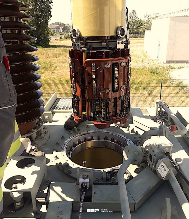
Figure 2 – Tap changer installed inside the transformer tank
2. LTC in a separate compartment:
The side-mounted LTC installed in a separate compartment have an enclosure installed independently from the transformer. It is bolted to the transformer tank’s side and connected to the tapped windings via a connection board.
Several LCT options have two compartments: one designated for the arcing switch and another for the selector and changeover switches. Other LCTs have all switches within a single compartment. They can be found in three-phase configurations, either Wye connected to be utilized at the neutral terminal of a three-phase transformer or totally insulated for application at the line terminal.
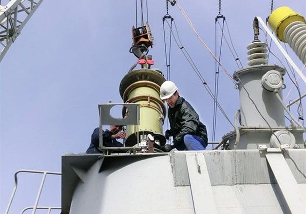
Figure 3 – Load tap changer installed in a separate compartment of a transformer
Types of LTC regulation
The primary categories of regulation are depicted in Figures 4, 5, 6, and 7 and are elaborated upon later.
LTC linear regulation:
Linear switching involves connecting tapped turns in series with the main winding so that their voltage increases the main winding’s voltage. This type does not require a changeover switch. Bypassing the tapped winding entirely occurs at the lowest voltage position.
Any of the available tap positions can be used as the rated position.
Figure 4 – Linear LTC regulation
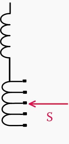
Where:
- S = selector switch,
- C = changeover switch, and
- R = reversing switch.
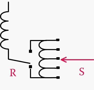
Plus–minus (reversing) regulation:
With a reversing regulation, the main winding and the entire tapped winding can be connected in either an additive or reversed polarity way. In relation to the main winding, the voltage of the tapped turns can be increased or decreased. At the neutral (midrange) voltage position, the tapped winding is completely bypassed. It is common for the middle position to be the rated one.
A total of two times the number of positions in the tapped winding plus one equals the total number of positions that can be filled.
Figure 5 – Reversing LTC regulation
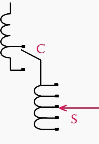
Coarse–precise regulation:
Coarse-precise regulation is characterized as a two-stage linear regulation, whereby the initial coarse stage comprises numerous turns that can be entirely bypassed by the changeover selector. The turns are depicted as a singular loop in the upper coil of the illustration (Figure 6). Precise regulation is accomplished using the selector switch. The coarse portion typically comprises the same number of turns as the tapped winding, plus an additional section.
The total number of available positions is double the number of sections in the tapped winding, plus one.
Figure 6 – Coarse–fine LTC regulation
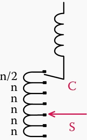
Bias winding regulation:
The bias winding regulation type resembles the coarse-precise method, except that the bias winding comprises half the number of turns of one section of the tapping winding. It serves to offer half steps between the primary tap steps. Consequently, the overall quantity of accessible places is double the number of sections in the tapped winding, plus one.
The bias winding technique can be integrated with the reversing scheme to yield double the number of positions (four times the number of sections in the tapped winding plus one), albeit at the cost of including an additional switch and multiplying the complexity of the switching and driving mechanism.
The tap selection switch, although not depicted in the Figure 7, is often a circular switch designed to facilitate a seamless transition between tap voltages during the operation of the changeover or reversing switch.
Figure 7 – Bias winding LTC regulation
Principle of Load Tap Changer operation
The load tap changer must be able to switch between tap positions without disrupting the current flow to the load at any moment. Consequently, it must adhere to a “make-before-break” switching sequence. Conversely, it must not, under any circumstances, generate a short circuit between any two terminals of the transformer winding.
This indicates that during the make-before-break time, a mechanism must exist that prevents the shorting of the turns.
Two principal methods are employed to achieve this.
1. Resistive switching
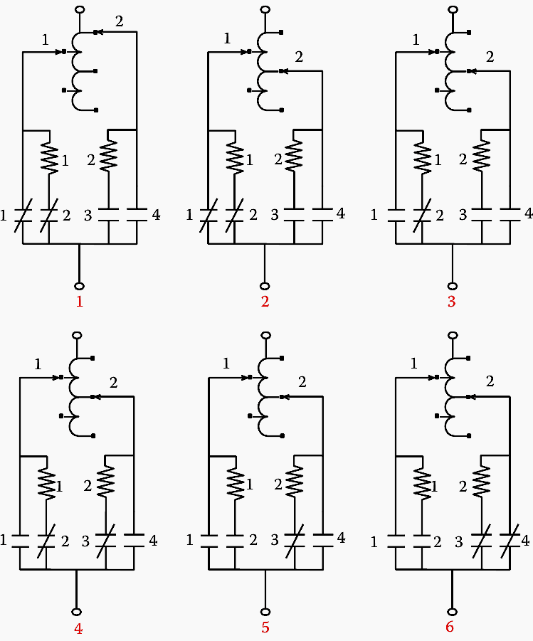
An illustration of a six-step switching process is presented in Figure 8. This specific type of tap changer features two selector switches and an arcing switch with four contacts.
Step 1: Step 1 of the Figure 8 illustrates the steady state of the tap changer just prior to the switching operation. The load current is passing through contact #1 and selector #1. We shall designate that position as tap #2.
Step 2: At step 2, the non-conducting selector has transitioned two positions downward, from position 1 to position 3. The current continues to flow in contact #1 and selector #1.
Step 3: At step 3, contact #1 opens, allowing current to pass through resistor #1 and selector #1.
Step 4: At step 4, contact #3 closes, causing the current to divide between the two resistors and the two selectors. A circulating current flows into the loop constrained by the two resistors and the loop’s reactance.
Step 5: 5. At step 5, contact #2 opens, interrupting the current in the resistor and selector #1. Arcing happens at that moment. The arc persists until the current intersects the zero line. At most, it can last one half cycle, which, at 60 Hz, equals to 8 ms. The typical arcing duration is approximately 5 to 6 milliseconds.
Step 6: At step 6, contact #4 closes, allowing the load current to bypass resistor #2 and flow directly to selector #2. The tap changer reached a steady state at tap position #3.
Figure 8 – Operations sequence in tap changers employing resistive switching. The selecting switches are the uppermost switches. The arcing switches are closed in the presence of a diagonal (shorting) line and open in its absence.
This transition necessitates that the resistors withstand the full load current plus , the circulating current throughout the transition from step 3 to step 5.
To decrease the energy absorption demand for the resistors, the duration of the entire transition must be decreased. These tap changers usually have rapid transitions.
Watch Video – Tap Changer and Motor Drive Unit Operation and Maintenance
2. Reactive switching with preventative autotransformer
A prevalent method for managing the transition between taps is using reactors in place of resistors. These reactors are not required to dissipate as much energy as the resistors. They primarily utilize reactive energy, which generates minimal heat.
Consequently, they can be engineered to withstand a full load in addition to the circulating current for extended durations, including continuous operation. Two reactors are required for each phase. They are often wound on a shared gapped core, resulting in reciprocal coupling. When connected in series, they function as an autotransformer.
The total number of positions provided by this design is double the number of sections in the tapped winding, plus one. This is the operational mechanism.
Figure 9 – Sequence of operations involved in tap changers using reactive switching
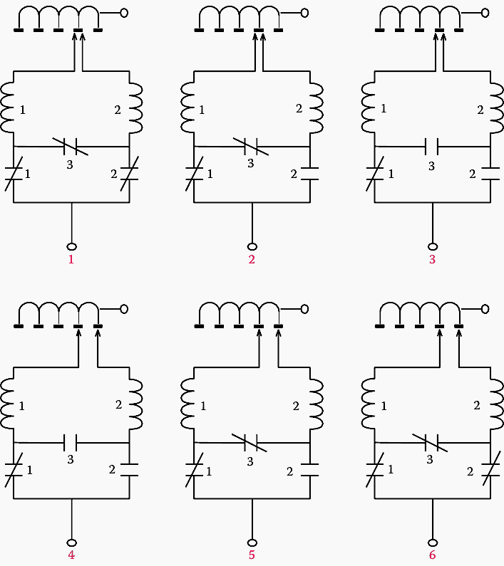
The operational procedure is illustrated in Figure 9. The tap changer comprises two selectors, two reactors (effectively one reactor with dual windings), two bypass switches (designated #1 and #2), and an arcing switch (#3).
Step 1: In step 1 of the Figure 9, the tap changer is in steady-state mode at tap position #2. The load current flows in the two selectors, the two reactors, and the bypass switches. Despite the arcing switch being closed, no current flows through it.
Step 2: The bypass switch opens. The current flows through switch #1 and thereafter splits between the two reactors and the two selectors.
Step 3: In the third phase, the arcing switch opens. All current flows through reactor 1 and selector 1. Arcing arises at that stage due to the interruption of current in the reactor.
Step 4: The right selector advances one position to the right, while it carries no current.
Step 5: The arcing switch closes, restoring current flow in reactor #2 and selector #2. Be aware that the two selectors are located on different taps. This induces a circulating current within the loop.
Step 6: The bypass switch #2 closes, resulting in a steady-state condition at tap position #1. The two ends of the reactors are connected in series between the two distinct taps. The voltage at their midpoint is halfway between the 2 taps. This stage is referred to as the “bridging position“, when the reactors bridge between the two taps.
It may also produce audible noise in the transformer.
Further Study – Understanding Vector Group of Transformer (Part 1)
Further Study – Understanding Vector Group of Transformer (Part 2)
Related electrical guides & articles


Edvard Csanyi
Hi, I'm an electrical engineer, programmer and founder of EEP - Electrical Engineering Portal. I worked twelve years at Schneider Electric in the position of technical support for low- and medium-voltage projects and the design of busbar trunking systems.I'm highly specialized in the design of LV/MV switchgear and low-voltage, high-power busbar trunking (<6300A) in substations, commercial buildings and industry facilities. I'm also a professional in AutoCAD programming.
Profile: Edvard Csanyi

Best website for all engineers
Hello Edvard,
Data presented are really very informative and helpful.
Best regards to EEP
Thank you, Renato. I’m glad you find this article useful!