
Estimated Study Time: 28 minutes
Interlocking in substations
Interlocking in substations is a critical aspect of power system protection and control, designed to ensure the safe and efficient operation of substation equipment. The primary objective of interlocking is to prevent hazardous situations, such as energizing an earthed circuit or operating isolators under load.
 What is Interlocking in substations, and what is it for?
By enforcing logical and mechanical constraints, interlocking schemes minimize human error and reduce the risk of system failures.
As substations evolve into smarter grids, modern systems increasingly employ software-based interlocking, integrated with SCADA (Supervisory Control and Data Acquisition) and RTU (Remote Terminal Unit) platforms. Additionally, the use of IEC 61850-based interlocking with GOOSE (Generic Object-Oriented Substation Event) messaging has enhanced system reliability, speed, and interoperability.
Interlocking schemes are categorized into electrical, mechanical, and software-based logical interlocking. Electrical interlocking uses auxiliary contacts and relays, mechanical interlocking employs physical locks, keys, and cam-operated devices, while logical interlocking is implemented using PLCs (Programmable Logic Controllers) or SCADA logic.
Each type has its specific role in ensuring operational safety and system reliability.
The role of GOOSE messaging in IEC 61850-based interlocking is also discussed, illustrating how modern substations achieve faster, more flexible, and more efficient protection and control.
By the end of this article, readers will gain valuable insights into how interlocking enhances safety, system reliability, and operational efficiency in substations.
- What is Interlocking in Substations?
- Why Interlocking is Essential in Substations
- Interlocking Example for a 132kV Line Bay:
- Logical (Software-Based) Interlocking:
- Software Logic Flow for Interlocking Using IEC 61850 (GOOSE Messaging) and Protocols
- BONUS (PDF) 🔗 Download The Essential Reference Guide for Electrical Engineers
1. What is Interlocking in Substations?
Interlocking is a critical safety mechanism implemented in substations to ensure the safe operation of various control devices. To fully understand the concept of interlocking, it is essential to first understand the functions, operational requirements, and characteristics of key substation equipment. Interlocking ensures that substation equipment is operated in a specific, predefined sequence.
Failure to follow this sequence can result in severe equipment damage, faults, or hazardous conditions. Therefore, network engineers must be familiar with the sequence of operation for various control devices.
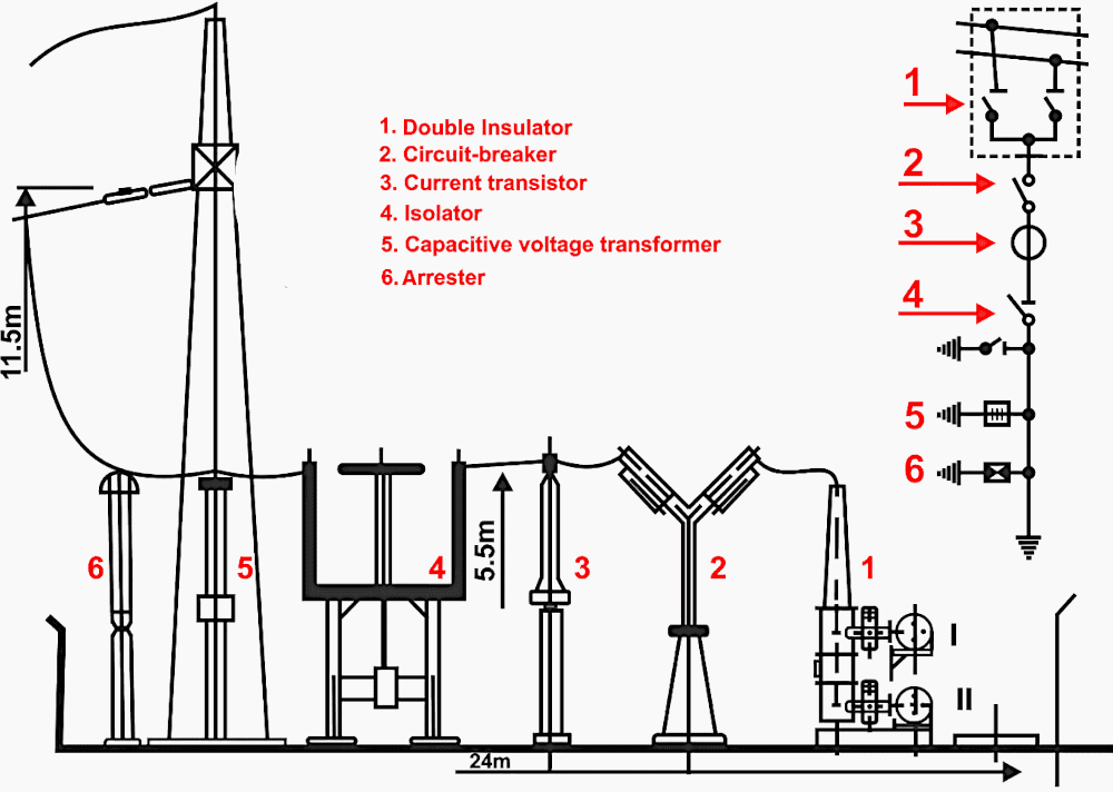
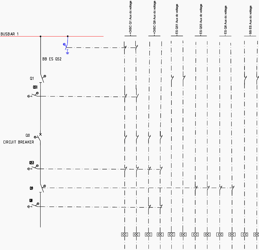
Figure 1 – Substation Components Depicted in SLD and Elevation Plan for a Double Bus Single Breaker Scheme Types of Interlocking
1.1 Key Substation Equipment Involved in Interlocking
1.1.1 Isolator (Disconnector)
Definition: An isolator (or disconnector) is an off-load device, meaning it does not have the capability to break load current or fault current. Its primary function is to provide a visible physical break in the circuit for maintenance purposes.
Operation: Before operating an isolator, it must be ensured that no current is flowing through the circuit.
Interlocking Requirement: To avoid the risk of operating the isolator under load, interlocking ensures that the isolator can only be operated after the circuit breaker has opened and interrupted the current flow.
Figure 2 – High voltage disconnector

1.1.2 Circuit Breaker
Definition: A circuit breaker is a device capable of making, carrying, and breaking current under both normal and fault conditions. Unlike isolators, circuit breakers have the capacity to interrupt current flow.
Operation: Since the circuit breaker can handle load current and fault current, it must be operated before the isolator to ensure that the circuit is de-energized. The circuit breaker can operate independently of the isolator’s status.
Interlocking Requirement: Interlocking logic ensures that the isolator cannot be closed or opened while the circuit ◦ breaker is in the closed position. This prevents the operator from inadvertently opening or closing the isolator under load conditions.
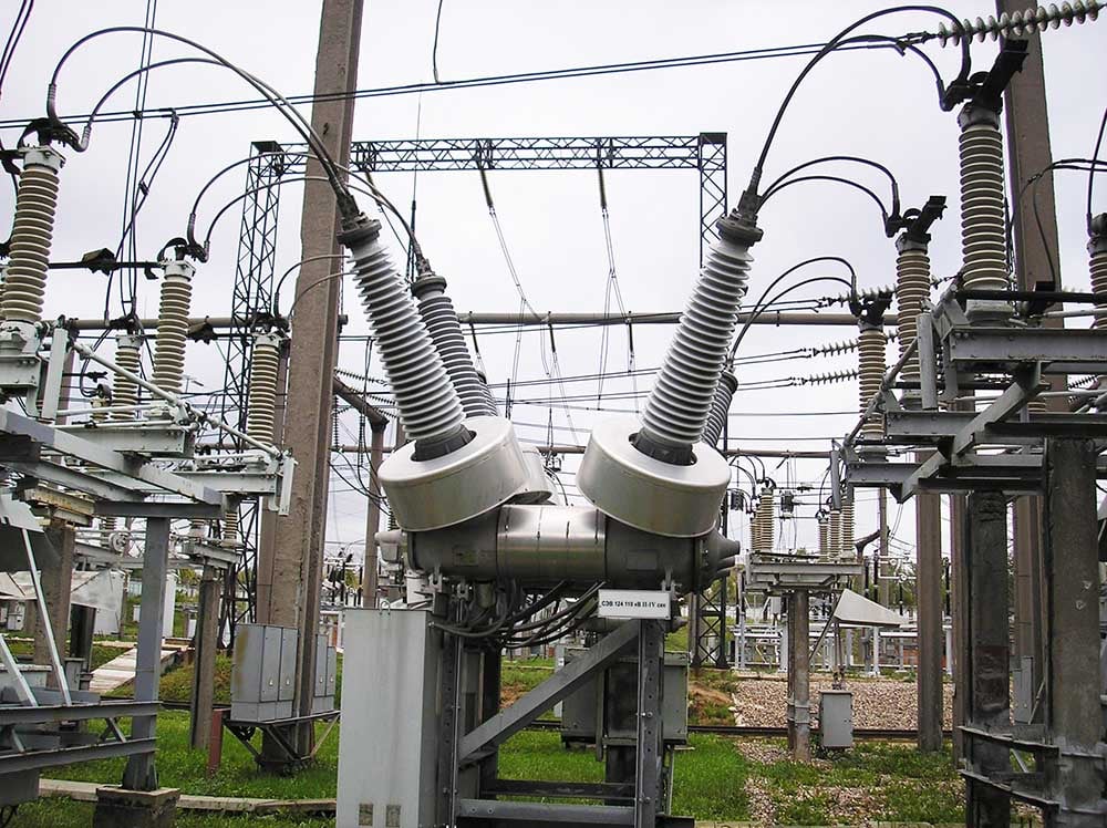
Figure 3 – 220kV SF6 circuit breaker
1.1.3 Earth Switch
Definition: An earth switch is used to ground equipment during maintenance, discharging any residual static charges, and protecting against emergency re-energization of the system.
Operation: Before operating an earth switch, it must be confirmed that the circuit is completely isolated from the power source. This means that the associated isolator must be in the open position.
Interlocking Requirement: To ensure safe operation, interlocking prevents the earth switch from being closed while the isolator is in the closed position. This is essential to protect operators from inadvertent grounding of a live circuit. Mechanical and electrical interlocks are used to ensure the proper sequence of operation.
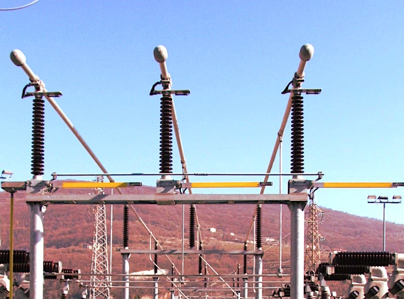
Figure 4 – High-voltage earthing switch
1.2 Electrical Interlocking
Definition: Electrical interlocking uses auxiliary contacts of substation devices to control the status and operation of other devices. This type of interlocking is achieved through electrical wiring and control logic.
Working Principle: The control circuit for an earth switch’s closing mechanism includes a series connection with a normally close auxiliary contact of the associated isolator. When the isolator is open, its auxiliary contact is closed, allowing the control circuit to be complete when the operator presses the close button for the earth switch.
However, if the isolator is in the closed position, the auxiliary contact remains open, thereby breaking the circuit and preventing the earth switch from closing, even if a close command is issued.
1.3 Mechanical Interlocking
Definition: Mechanical interlocking involves the physical design of substation equipment to prevent unsafe operations. It relies on levers, rods, and physical constraints rather than electrical control circuits.
Working Principle: Mechanical interlocking is achieved by physically linking the movement of one device (e.g., an isolator) to the movement of another (e.g., an earth switch). If the isolator is in a closed position, the mechanical design prevents the earth switch from closing.
This can be achieved using interlocking keys, cams, or physical obstructions.
Figure 5 – Example of electrical interlocking diagram
2. Why Interlocking is Essential in Substations
Interlocking is essential in power substations for the following reasons:
1. Safety: Prevents unsafe operations, such as the inadvertent closure of earth switches or opening of isolators under load conditions.
2. Equipment Protection: Ensures substation equipment like circuit breakers, isolators, and transformers are protected from mechanical and thermal damage caused by improper operation.
3. Error Prevention: Reduces the risk of human error during manual operations, as interlocking restricts operators from executing unsafe commands.
4. Compliance: Ensures substation operations adhere to industry safety standards and operational guidelines.
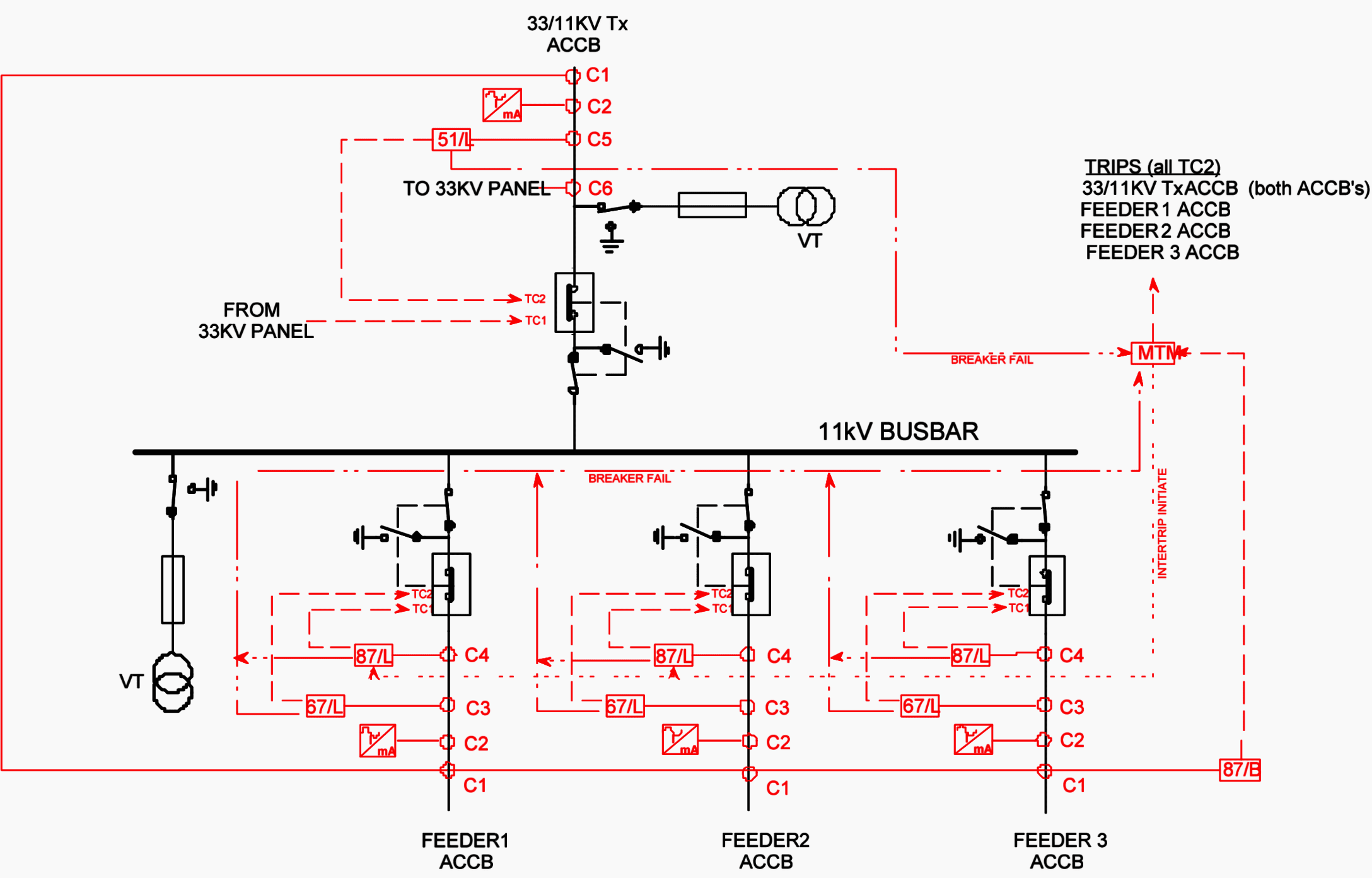
Figure 6 – Interlocking diagram for 132kV single bus single breaker scheme
3. Interlocking Example for a 132kV Line Bay
Consider the scenario of a simple single bus single breaker scheme. This arrangement includes essential components such as a busbar isolator, line isolator, circuit breaker, busbar isolator earth switch, busbar earth switch, and line earth switch.
3.1 Energizing the Line
1. Grounding Removal:
The first step in energizing the line is to open the busbar isolator earth switch and the line isolator earth switch. This action removes all grounding connections (Q8, Q53 & Q51) from the system. It is assumed that the busbar is already live, which means the busbar earth switch is already in the open position.
Additionally, ensure that the circuit breaker is in the open position to avoid any unintended current flow during the process.
Related electrical guides & articles


Muhammad Kashif
Muhammad Kashif Shamshad is an Electrical Engineer and has more than 17 years of experience in operation & maintenance, erection, testing project management, consultancy, supervision, and commissioning of Power Plant, GIS, and AIS high voltage substations ranging up to 500 kV HVAC & ±660kV HVDC more than ten years experience is with Siemens Saudi Arabia.Profile: Muhammad Kashif
