
Estimated Study Time: 30 minutes
Substation Automation at a Glance
Substation automation system, or shorten SAS, is not a new term, its been in use for the last 30 years. However, substation automation as a technology has rapidly evolved in the last 10 years and nowadays represents a highly advanced system capable of controlling every single process of a power substation.
 What is the substation automation system (SAS) and what you MUST know about it
In a few years, the next generation of substations will begin to massively appear in many countries worldwide. At that time, the station bus will connect the IEDs that are used for protection, control, and monitoring with the devices that are located at the station level, and the process bus will connect the bay units with the devices that are located in the switchyard.
In addition, because it will be based on the IEC 61850 architecture, conventional wiring will be done away with, and binary and analogue signals will be delivered and received via the communications interface. In addition, the technologies of sensor and traditional instruments transformers are going to coexist in new installations, as well as in an increasing number of secondary retrofit or extension installations. This is going to be the case for both types of installations.
In conclusion, the utilization of Ethernet network architectures would be expanded in order to facilitate communication inside substations as well as between those substations and the control center.
Ok, let’s get into the subject, and that’s the basics of Substation Automation. To begin, let’s discuss the fundamental concepts that underpin such a system. After that, we’ll examine the most important tasks that an SAS completes, and the final section will focus on the primary components of an SAS.
1. What Makes SAS?
The first one is primary equipment. The term “primary equipment” refers to a bunch of high-voltage components whose individual sizes are determined by the voltages at which the substation operates. In addition, every electric substation is made up of a large number of low-voltage components that are on the smaller side.
The secondary system is the collective name for all of these low-voltage components.
The group of high voltage equipment consists of changing-state equipment or switchgear (circuit breakers, disconnectors, and earthing switches used to maintain or to interrupt the energy flux from/to transmission lines or load feeders connected to the substation), instrument transformers (voltage transformers and current transformers) that reflect voltages and currents present at high voltage terminals of primary equipment, and also, in most cases, power transformers to change the voltage of the primary equipment’s high voltage terminals.
The foundation of substation automation systems, also known as SASs, is a large amount of specialized software that is kept in hardware components that are part of a set of substation secondary components.
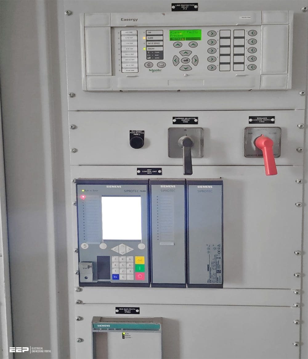
Figure 1 – Advanced relay control and protection panel used in SASs
SASs can be built utilizing a straightforward method that makes use of more contemporary technology by integrating three distinct sets of devices together with two local area networks.
The process devices group is comprised of analog-to-digital converters as well as actuator devices, and its primary function is to facilitate the transition between SAS and high voltage equipment. The term “inteface devices” refers to a collection of “Intelligent Electronic Devices“, or “IEDs,” which are able to receive and process signals that are transmitted from high voltage apparatus.
The application devices group is comprised of all of the computers and other components that are necessary to successfully operate control features and interface with both internal and external subsystems.
Figure 2 – Simplified model of a substation automation system (SAS)
*** NCC stands for Network Control Center
Go back to the Contents Table ↑
2. Substation Automation Functions
The following are the most significant functions that an SAS performs:
Control Function:
- Selecting, opening and closing circuit breakers and disconnectors.
- Commands to block and unblock.
- Giving release information to circuit breakers and disconnectors for securing the opening and closing actions.
Monitoring Function:
- Showing substation configuration with position indication (open or closed) of circuit breakers and disconnectors based on signals coming from their own position contacts.
- Acquiring and process data coming from power transformers and other primary equipment related to condition operation.
- Displaying substation events including information regarding switchgear opening and closing actions due to any external cause, such as the activation/operation of a protective relay.
Alarming Function:
- Announcing to a substation operator all adverse conditions that may represent a risk to substation integrity.
- Preventing trouble with SAS operation.
Measurement Function:
- Acquiring and showing current values of electrical or other relevant parameters.
- Giving indications of energy flows through substation primary equipment and transmission lines.
Setting and Monitoring of Protective Relays:
- Allowing changes on operating parameters of protective relays.
- Giving alarm signals when any undesirable condition may affect the right relay performance.
Control and Monitoring of the Auxiliary Power System:
- Displaying screens/drawings showing the configuration of the auxiliary power system.
- Allowing selection and execution of control commands.
- Driving automatic transfer switches.
- Managing interlocking logics.
- Supervising AC/DC power source conditions.
- Giving alarm signals from abnormal conditions.
Voltage Regulation:
- Monitoring actual voltage value on the power system.
- Changing the position of the tap‐changer of power transformers.
- Giving alarms and signals.
The operator is presented with control and monitoring information via a graphical interface that displays overview diagrams, control means, alerts, measurement, trends, and event sequences on user-friendly screens.
Related electrical guides & articles


Edvard Csanyi
Hi, I'm an electrical engineer, programmer and founder of EEP - Electrical Engineering Portal. I worked twelve years at Schneider Electric in the position of technical support for low- and medium-voltage projects and the design of busbar trunking systems.I'm highly specialized in the design of LV/MV switchgear and low-voltage, high-power busbar trunking (<6300A) in substations, commercial buildings and industry facilities. I'm also a professional in AutoCAD programming.
Profile: Edvard Csanyi
