Parallel-resonance phenomena
The use of both capacitive and inductive devices in distribution systems leads to resonance phenomena, resulting in extremely high or low impedance values. These variations in impedance modify the current and voltage in the distribution system. Here we will discuss only parallel-resonance phenomena, which are the most frequent.
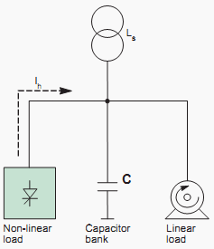
Consider the simplified diagram below, showing an installation made up of:
- A transformer supplying power,
- Linear loads,
- Non-linear loads causing harmonic currents,
- Power factor correction capacitors.
Harmonics have a major economic impact on installations in that they cause:
- Higher energy bills,
- Premature ageing of equipment,
- Drops in productivity
For harmonic-analysis purposes, the equivalent diagram is shown below:
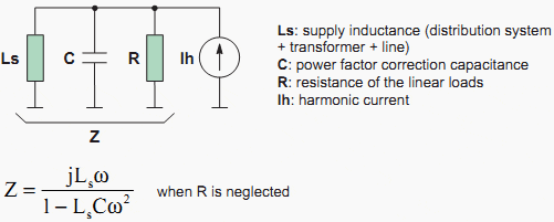
Resonance occurs when the denominator 1-LsCω2 approaches zero. The corresponding frequency is called the resonant frequency of the circuit. At this frequency, the impedance is at its maximum value, resulting in considerable voltage harmonics and consequently major voltage distortion. This voltage distortion is accompanied by the circulation of harmonic currents in the Ls + C circuit which are greater than the injected harmonic currents.
The distribution system and the power factor correction capacitors are subjected to considerable harmonic currents, resulting in the risk of overloads.
Reference // Harmonic detection and filtering – Schneider Electric





sir,
Wanted to know the following
If a capacitor bank is connected on 415V side of distribution transformer with on / off switching, will there be a change in pf recorded by meters at consumer end ( say 100 consumers 1Ph and 3Ph are connected to this transfomer.) when the capacitor bank is switched on / off
Sir, can u explain further the following:
to reduce the effect of harmonics or noise transferring from one winding to other (due to coupling), a earthed copper shield is provided,
the reduction of harmonics is related with the resonance, but i can/t understand, what is going there actually..
can you pls explain me.
Yes, is because when you have harmonic currents in an transformer, you have Load Loses in the core,
and these are below:
PLL= I^2R+ Pec
PLL= Load Loses.
Pec= Loses by Eddy current.
I^2R= Copper Loses.
If you put a copper lead in the core, this conductor filtering the eddy-current unto earth.