
Estimated Study Time: 4 minutes
Grading operating times of the relays
What are time grading and relay coordination in protection philosophy? Let’s try to figure out how to grade (or rank) the relays’ operation times so that the one nearest the problem operates first. In Radial Distribution Systems, time-graded protection works well. Systems that begin with an electrical source at the top and end with a load at the bottom are known as radial distribution.
 What is Time Grading in Relay Protection
Figure 1 shows how time-graded protection is achieved using overcurrent relays that have either inverse time or definite time characteristics. Operating time of inverse time relays is reduced as fault current magnitude grows, in contrast to that of finite time elements (very flat at magnitude curves), which are unaffected by fault current magnitude.
In radial networks, inverse time protection is employed when changes in network configurations do not significantly affect short-circuit power variations or when there is a large difference between the size of the short-circuit current at the beginning of the network and the feeder.
With inverse time characteristics, the protection mechanism can operate faster for larger fault current magnitudes closer to the power source in certain situations.
Figure 1 – Inverse overcurrent protection
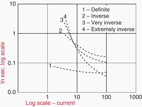
Inverse time qualities also make it easier to achieve time grading coordination with fuses. There is a somewhat flat definite time characteristic, however there is a spectrum of steepness from “very inverse” to “extremely inverse” for the inverse characteristics.
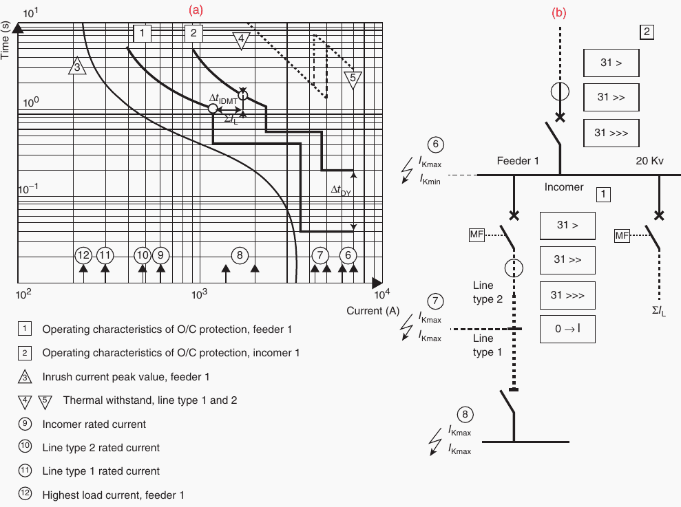
Figure 2a, curves 1 and 2, shows the diagram with the protective devices placed first. To the right of the first curve, you must lay out the thermal capability of the protected equipment. Ensure that all additional protective curves are positioned to the right of the transformers’ and cables’ thermal characteristics and do not intersect within 0.4 seconds of each other.
The fault levels (A) along the single-line figure in Figure 2b are shown by the numbers 6–8 (going from 8 to 6) at the bottom of the graph. That helps choose the right setting based on how bad the fault is
The equipment ratings, which must be kept protected, are shown by the numbers 9–12.
Figure 2 – Time graded relay coordination
Related electrical guides & articles


Edvard Csanyi
Hi, I'm an electrical engineer, programmer and founder of EEP - Electrical Engineering Portal. I worked twelve years at Schneider Electric in the position of technical support for low- and medium-voltage projects and the design of busbar trunking systems.I'm highly specialized in the design of LV/MV switchgear and low-voltage, high-power busbar trunking (<6300A) in substations, commercial buildings and industry facilities. I'm also a professional in AutoCAD programming.
Profile: Edvard Csanyi
