
Estimated Study Time: 11 minutes
Switchgear bays
It’s not always an easy task to explain what is what in high voltage substations. Shapes of the major elements are mostly similar through substations, but there are also combinations of two and more elements with integrated functions.
 What is what in outdoor HV substation? How to identify elements by shape and function? (photo credit: Geoff Collins via Flickr)
This technical article explains the basic elements and their shapes/functions you can see in outdoor high voltage substations.
Each operating facility inside a substation fulfils an important function, varying in shape and size depending on its location and purpose. They ensure that the total installation can be operated securely and reliably.
The combination of the devices surrounding a circuit breaker – disconnectors and earthing switches and combined instrument transformers that form a functional unit with the circuit breaker – is called the switchgear bay.
At the centre of each switchgear bay is the circuit breaker, which can interrupt the current both in normal operating conditions and in case of disturbances. The switchgear bay is connected to the other operating facilities via disconnectors with an integrated earthing switch.
The combined instrument transformer reports information on the current and voltage to the protection and control systems.
According to the function, a distinction is made between:
Line switchgear bay – this connects the high voltage power line with the busbars.
Transformer switchgear bay – this switchgear bay connects the transformer with the busbars. Noteworthy is that the transformer is connected directly and not by means of a disconnector.
Coupler bay – this switchgear bay forms a flexible connection with the busbars.
How is an underground cable connected? When power is supplied to the substation via a high-voltage underground cable instead of an overhead line, the overhead line portal is replaced by the cable portal. In addition, specific facilities also need to be installed to operate the cable.
These are compensation reactors which regulate the reactive power needed by the cable, as well as surge arresters.
Substation elements
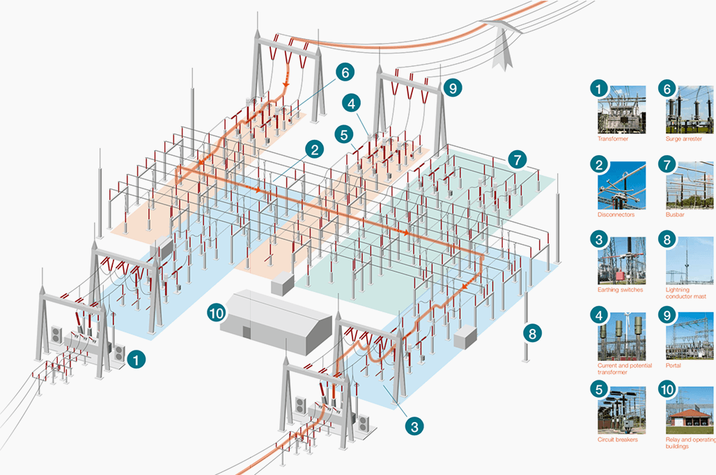
Following the layout above, let’s see the shapes and functions of ten major components you can see in most HV substations. Note that listed elements may have a little bit different look depending on technology and manufacturer.
- Power transformer
- Disconnectors
- Earthing switches
- Current and potential transformers
- Circuit breakers
- Surge arrester
- Busbars
- Lightning conductor mast
- Portal
- Relay and operating buildings
1. Power transformer
The maximum voltage used to transport electric current in the European transmission system is 380,000 volts (380 kV) in order to keep the losses as low as possible.
But how are these 380,000 volts brought down to the voltage used in households? Transformers take care of this change in voltage. The large jump from high voltage (380,000 volts) to household voltage (230 volts) can, however, not be made in a single bound.
The grids using these different voltage levels are all connected by substations.
Transformers that adjust voltage levels from 380 kV to 110 kV – meaning from the voltage level of the transmission system to the distribution system – are about as large as a personal garage. Both on the outside and the inside, they are mainly constructed in metal.
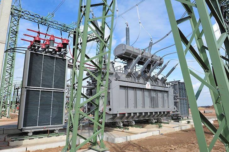
A transformer has a primary and a secondary side. On the primary side, the power on the high voltage side ows through a large coil. This coil is wrapped around a large iron core. The magnetic field that is created inside the transformer induces a current in the coil on the secondary side. As the proportions of the coils are different, the voltage is lowered to 110 kV.
Inside the transformer, oil is used as insulation and a means to dissipate heat. The oil is cooled in large heat exchangers next to the transformer, so that the latter can be properly cooled in each operational state.
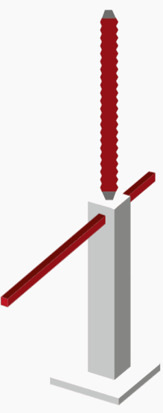
2. Disconnectors
Disconnectors can be found almost everywhere in a substation. Depending on the location, these are feeder or busbar disconnectors. Their purpose is to open the electrical circuit and to completely isolate certain system components from the rest of the installation.
They do not connect or disconnect the current. Within your own home, opening a disconnector can be as simple as unplugging a switched-off appliance or device.

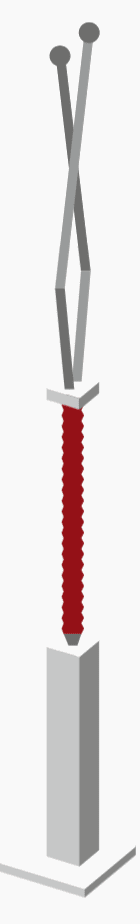
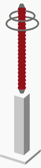
3. Earthing switches
An earthing switch provides a safe and reliable ground connection for a deactivated and therefore voltage-free system component. It prevents the danger occurred through the charge processes.
In combination with the disconnectors, they create a safe working environment inside the substation.

4. Current and potential transformers
For the secure operation of a substation, it is necessary to know of the state of the grid system at all times. The data needed to determine this state are supplied by current and potential transformers.
Additionally, these data are processed by the protection and control systems, so that they can respond automatically in case of disturbances.
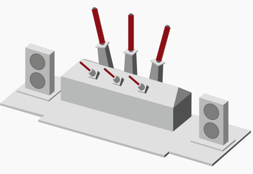
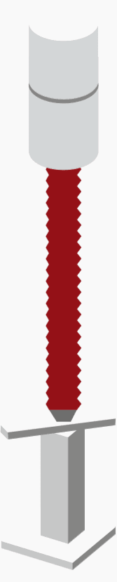
5. Circuit breakers

The circuit breaker is the high-voltage equivalent of a light switch and a miniature circuit breaker. It activates and de-activates lines and system components, irrespective of whether there is a normal load current or a disturbance.
Aside from the transformer, this is the most important high-voltage device of the substation.

6. Surge arrester
Surge arresters can often be found at the end of an overhead line or a cable. They limit over-voltages or surges, which are brief voltages that are significantly higher than the normal voltage and can be caused, for example, by a lightning stroke.
By limiting the voltage to a normal level, the devices in the substation can be protected without interrupting the supply.

7. Busbars

The busbar is the backbone of the substation. Tubes connect the different switchgear bays and take care of power transmission within the substation. In order to increase the fail-safe performance and more flexibly control the transmission of electricity, there are usually multiple busbars.
These can be connected in many different ways.

8. Lightning conductor mast

The lightning conductor mast is not part of the operating facilities of the substation. Nevertheless, it is an essential component. Given the often open area and the many tall metal devices, lightning strokes are not unlikely in a substation. In order to protect the devices and ensure the electricity supply, substations are equipped with several high lightning conductor masts.
Like a lightning rod on a house, it serves to conduct the lightning stroke to the earth in a controlled manner without exposing personnel and operating facilities to danger.
Protection against lightning strokes: The voltage of a lightning stroke can amount to 100 million volts and has to be safely conducted to earth to avoid damage to the substation.

9. Portal
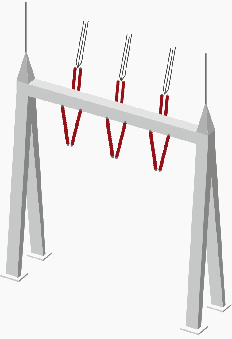
Aside from operating facilities and lightning conductor masts, there is another noticeable construction within the substation – the portal.
Busbar portals, however, act as supports on which the tubular busbars are mounted and insulated.

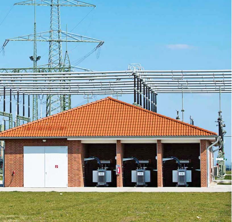
10. Relay and operating buildings
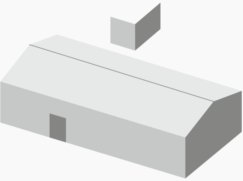
Inside the substation there are also relay and operating buildings. Relay buildings mainly include protection and control components. In order to limit the distance to the controlled devices, there can be multiple relay buildings in-side a single substation.
The operating building contains the other components of the control system, communications system and the storage, break and restrooms.
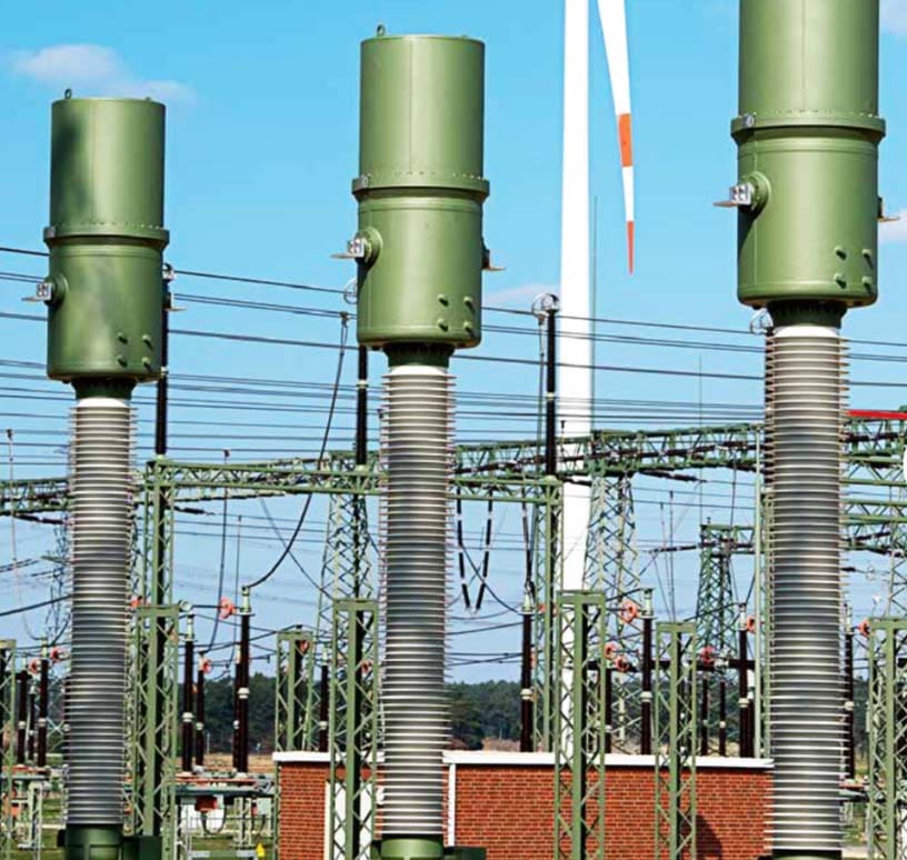
HV Substations around the world… 125kv, 66kv, 33kv
Reference // How substations work by 50Hertz Transmission GmbH
Related electrical guides & articles


Edvard Csanyi
Hi, I'm an electrical engineer, programmer and founder of EEP - Electrical Engineering Portal. I worked twelve years at Schneider Electric in the position of technical support for low- and medium-voltage projects and the design of busbar trunking systems.I'm highly specialized in the design of LV/MV switchgear and low-voltage, high-power busbar trunking (<6300A) in substations, commercial buildings and industry facilities. I'm also a professional in AutoCAD programming.
Profile: Edvard Csanyi

it is a highly engineered site
Thank you
Great article
Great Article. Thank you
Can I have your valuable articles in PDF format please?
I’m so impress with all the outrageous and exclusive Jon welldone,by the EEP group of Company. I wish to learn more mad to work with the Company
Hello. Great work, but … on the energy flow, the lower voltage section, after the power transformer, should go through the Relay and operating building, isn’t’? There we find the medium voltage bay, for example, no?
Thank you.
Don’t think so. In this case, in the building there is no MV switchgear, only protection / control panels, etc. Lower voltage energy from transformer ( = MV) is not presented in the plan, and goes to special dedicated switchgear, in another building (or open-yard).
I am really grateful to meet you, this is very informative and useful
Thanks
Edvard Csanyi…you’re the most effective professor I’ve ever known : your systematic and the way you explaining subjects are incredible. Thank you very much.
I really appreciated the knowledge shared by EEP and I m very interested in reading all your articles because they are very educative.Thanks Edvard for your support to younger Engineers
I wish to join the Premium membership but the link is not secured and I needed to use my VISA card. What can be done for me?
The article is very useful and the information is valuable for learning and practicing in the field. Thanks EEP.
Hi, Some 52 years ago I was engineer in charge of high voltage research with A. Reyrolle in U.K.
Reading about what you guys are doing today has blown me away. I am still not sure I comprehend
how High Voltage D.C. circuit breakers actually work. By the way I am now 84, but still like to read and
appreciate the advances that have taken place. In particular I would like to know a VSC valve functions.
Kind regards,
Alan
Good luck Allen. That was great to see your attitude.