Design constraints
Several key design constraints for grounding systems from the NEC are as follows. These are paraphrased from the code text:
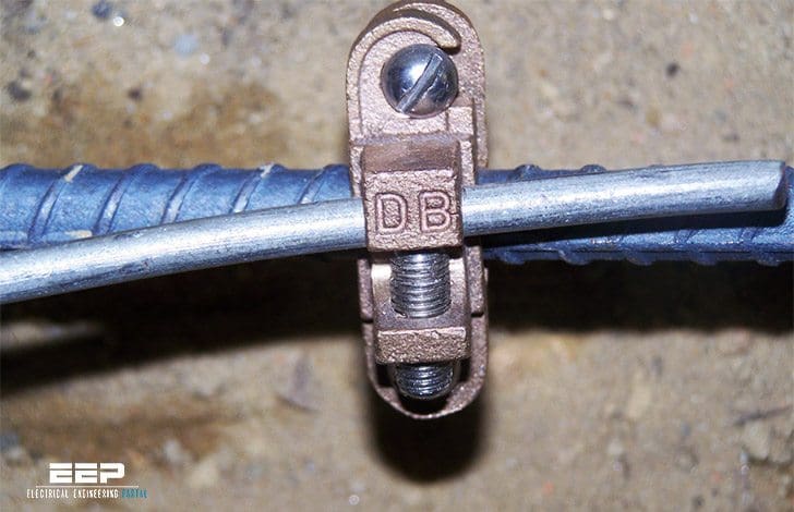
Ø Electrical systems that are grounded must be grounded in such a manner as to limit the voltage imposed by lightning, line surges, or unintentional contact with higher voltage lines and that will stabilize the voltage to earth during normal operation /Article 250.4(A)(1)/.
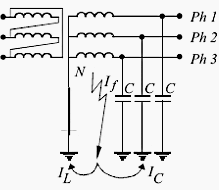
Ø If the system can be solidly grounded at 150 V to ground or less, it must be solidly grounded /Article 250.20(B)/. There is therefore no such system as a “120 V Ungrounded Delta” in use, even though such a system is physically possible.
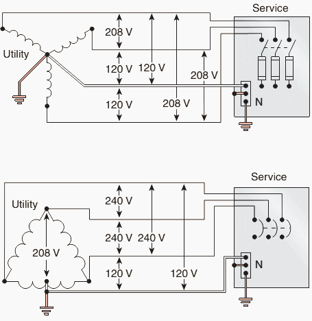
Ø If the system neutral carries current it must be solidly grounded /Article 250.20(B)/. This is indicative of single-phase loading and is typical for a 4-wire wye (figure 2 left) or center-tapped 4-wire delta (figure 2 right) system.
Ø Certain systems are permitted, but not required, to be solidly grounded. They are listed as electric systems used exclusively to supply industrial electric furnaces for melting, refining, tempering, and the like, separately derived systems used exclusively for rectifiers that supply only adjustable-speed industrial drives, and separately derived systems supplied by transformers that have a primary voltage rating less than 1000 volts provided that certain conditions are met /Article 250.21/.
Ø If a system 50-1000 VAC is not solidly-grounded, ground detectors must be installed on the system unless the voltage to ground is less than 120 V /Article 250.21/.
With notification of the ground-fault condition, rather than automatic interruption of the circuit, the operators of the process supplied by the ungrounded system can then take the necessary steps to effect an orderly shutdown, determine where the ground fault is located in the system, and can safely perform the necessary repair.
Ø Certain systems cannot be grounded. They are listed as circuits for electric cranes operating over combustible fibers in Class III locations as provided in Article 503.155, circuits within hazardous (classified) anesthetizing locations and other isolated power systems in health care facilities as provided in 517.61 and 517.160, circuits for equipment within electrolytic cell working zone as provided in Article 668, and secondary circuits of lighting systems as provided in 411.5(A) /Article 250.22/. Some of the requirements for hazardous locations and health care facilities are covered in section XVI.
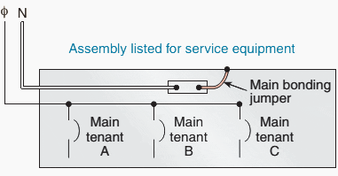
Ø For solidly-grounded systems, an unspliced main bonding jumper must be used to connect the equipment grounding conductor(s) and the service disconnect enclosure to the grounded conductor within the enclosure for each utility service disconnect /Article 250.24(B)/.
Ø For solidly-grounded systems, an unspliced system bonding jumper must be used to connect the equipment grounding conductor of a separately derived system to the grounded conductor. This connection must be made at any single point on the separately derived system from the source to the first system disconnecting means or overcurrent device /250.30(A)(1)/.
Ø A grounding connection on the load side of the main bonding or system bonding jumper on a solidly-grounded system is not permitted /Articles 240.24(A)(5), 250.30(A)/.
Ø Ground fault protection of equipment must be provided for solidly grounded wye electrical services, feeder disconnects on solidly-grounded wye systems, and building or structure disconnects on solidly-grounded wye systems under the following conditions:
- The voltage is greater than 150 V to ground, but does not exceed 600 V phase-to-phase.
- The utility service, feeder, or building or structure disconnect is rated 1000 A or more.
- The disconnect in question does not supply a fire pump or continuous industrial process.
Articles 215.10, 230.95, 240.13
Ø Where ground fault protection is required per Article 215.10 or 230.95 for a health care facility, an additional step of ground fault protection is required in the next downstream device toward the load, with the exception of circuits on the load side of an essential electrical system transfer switch and between on-site generating units for the essential electrical system and the essential electrical system transfer switches /Article 517.17/.
Ø The alternate source for an emergency or legally-required standby system is not required to have ground fault protection. For an emergency system, ground-fault indication is required /Articles 700.26, 701.17/.
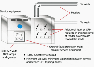
Ø All electrical equipment, wiring, and other electrically conductive material must be installed in a manner that creates a permanent, low-impedance path facilitating the operation of the overcurrent device. This circuit must be able to safely carry the ground fault current imposed upon it. /Article 250.4(A)(5)/.
Ø High-impedance grounded systems may utilized on AC systems of 480-1000 V where:
- Conditions of maintenance and supervision ensure that only qualified persons access the installation.
- Continuity of power is required.
- Ground detectors are installed on the system.
- Line-to-neutral loads are not served.
Article 250.36
Ø For systems over 1000 V:
- The system neutral for solidly-grounded systems may be a single point grounded or multigrounded neutral. Additional requirements for each of these arrangements apply /Article 250.184/.
- The system neutral derived from a grounding transformer may be used for grounding /Article 250.182/.
- The minimum insulation level for the neutral of a solidly-grounded system is 600 V. A bare neutral is permissible under certain conditions /Article 250.184 (A) (1)/.
- Impedance grounded neutral systems may be used where conditions 1, 3, and 4 for the use of highimpedance grounding on systems 480-1000 V above are met /Article 250.186/.
- The neutral conductor must be identified and fully insulated with the same phase insulation as the phase conductors /Article 250.186 (B)/.
- Zig-zag grounding transformers must not be installed on the load side of any system grounding connection /Article 450.5/.
Ø When a grounding transformer is used to provide the grounding for a 3 phase 4 wire system, the grounding transformer must not be provided with overcurrent protection independent of the main switch and common-trip overcurrent protection for the 3 phase, 4 wire system /Article 450.5 (A) (1)/. An overcurrent sensing device must be provided that will cause the main switch or common-trip overcurrent protection to open if the load on the grounding transformer exceeds 125% of its continuous current rating /Article 450.5 (A) (2)/.
Reference: System Grounding – Bill Brown, P.E., Square D Engineering Services





Being asked to provide a GFI on a feeder that is protected by a GFI main in a 1600A 480/277 3ph 4W switchboard. Main is 1600a GFI Branch feeder is 1200A. NEC 230.95 note 3 is not clear enough regarding protection of feeder.
What is the restrictions for passing the air duct,(Air Conditioning) in side an electrical room, for the electrical room it self ?