
Estimated Study Time: 5 minutes
Increasing reliability //
Redundancy is a useful method of increasing reliability and optimising the balance between operation effectiveness and expenditure. In the context of reliability, redundancy signifies that a system will continue to function satisfactorily in spite of the failure of some of the component parts.
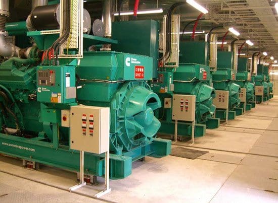
 What parallel redundancy does to the power distribution system? (photo credit: hipowersystems.com)
This resilience to failures is obtained by providing alternative paths of operation, by arranging selected elements of the system in parallel. Generally, alternative paths of operation can be achieved by following:
Standby Redundancy
Standby redundancy means that an alternative means of performing the function is provided but is inoperative until needed. It is switched on upon failure of the primary means of performing the function.
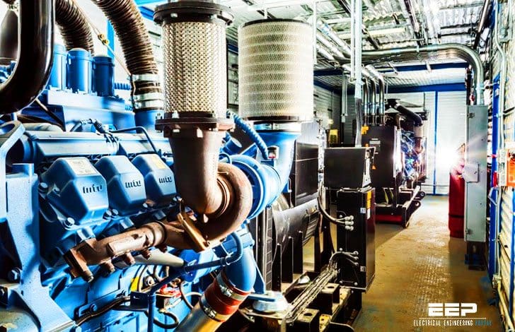
An example of standby redundancy would be the use of a standby generator in a building to ensure continuity of supply in case of a mains failure. The generator is not called for until it is needed when the power supply fails.
Such a scheme would not be suitable for a computer system, because data would be lost during the relatively long period required to start the standby generator.
Active or Parallel Redundancy
In active or parallel redundancy, all redundant units are operating simultaneously rather than being switched on when needed. The most obvious approach is to use two components, each capable of carrying the full load, so that if one should fail the other will take over – this is referred to as 1+1 redundancy.
For example, a 1+2 redundancy scheme would have two fully rated redundant units supporting the single operating unit and would require all three units to fail before the system fails. Because there is no interruption, active redundancy is suitable for computer installations.
N+1 and 1+1 Redundancy
The theory of redundancy is that should a component within a system fail, the system will continue to function because alternative paths are available for the system to operate.
In Figure 1 the system will function with either A1 or A2 operating. Should component A1 fail, the system will continue to function. This type of redundancy is termed 1+1, as there is 100% redundancy available.
In the system shown in Figure 2 two out of the three components are required for the system to function and there is one redundant component. In this scenario, the system would be called 2+1. In each case, the first number refers to the number of components required for the system to function correctly and the second number refers to the number of standby components available.
It is possible to have many redundant components that would significantly improve the reliability of the system. However, this would also be expensive and in most applications a balance is achieved between reliability and economics.
Load testing a 500kVA generator (VIDEO)
Reference // A Good Practice Guide to Electrical Design – Copper Development Association (Download guide)
Related electrical guides & articles


Edvard Csanyi
Hi, I'm an electrical engineer, programmer and founder of EEP - Electrical Engineering Portal. I worked twelve years at Schneider Electric in the position of technical support for low- and medium-voltage projects and the design of busbar trunking systems.I'm highly specialized in the design of LV/MV switchgear and low-voltage, high-power busbar trunking (<6300A) in substations, commercial buildings and industry facilities. I'm also a professional in AutoCAD programming.
Profile: Edvard Csanyi

I want to build my career with Electrical and Electronic Engineering with practical work
Thanks Edvard Csanyi
Such a great information about electrical system
Thanks
This is useful in clearing concept of redundancy.